
Wireless detecting system for water flow

A flow and wireless technology, applied in the direction of fluid velocity measurement, signal transmission system, measurement flow/mass flow, etc., can solve the problems of time-consuming, laborious, cumbersome testing, etc., and achieve the effect of simplifying the process, improving the accuracy of the test, and simplifying the speed measurement program

Inactive Publication Date: 2016-01-20
张广海
View PDF5 Cites 1 Cited by
  • Summary
  • Abstract
  • Description
  • Claims
  • Application Information

AI Technical Summary

Problems solved by technology

The test is very tedious and time-consuming

Method used


Image

  • Wireless detecting system for water flow
  • Wireless detecting system for water flow
  • Wireless detecting system for water flow

Examples


Embodiment Construction

[0021] Below in conjunction with accompanying drawing, the present invention is described in further detail:

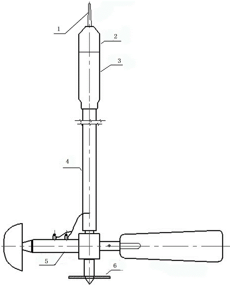
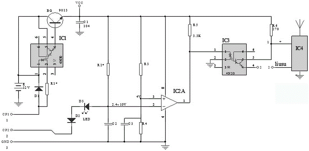
[0022] A wireless test system for water flow in the present invention includes a measuring terminal and a receiving recorder. The measurement terminal includes a suspension rod 4 and a current meter 5 arranged at the bottom of the suspension rod 4. An electrical appliance compartment 3 is arranged on the top of the suspension lever 4. An integrated circuit board is arranged in the electrical appliance compartment 3. The integrated circuit board is integrated with a connected power supply unit, The power supply electronic switch unit, the signal processing unit, the transmission electronic switch unit and the modulation transmission unit, and the transmission antenna 1 connected to the modulation transmission unit is arranged on the top of the electrical appliance compartment 3 . The receiving recorder includes a microprocessor, a wireless receiving module and a displa...


PUM


Abstract

The invention discloses a wireless detecting system for water flow. The wireless detecting system comprises a measuring terminal and a receiving recorder. The measuring terminal comprises a suspending rod and a flow speed instrument arranged at the bottom of the suspending rod. An electric appliance bin is arranged at the top of the suspending rod, an integrated circuit board is arranged in the electric appliance bin, and a power supply unit, a power source electronic switch unit, a signal processing unit, an emitting electronic switch unit and a modulating emitting unit which are connected are integrated on the integrated circuit board. An emitting antenna connected with the modulating emitting unit is arranged at the top of the electric appliance bin. The receiving recorder comprises a microprocessor, a wireless receiving module and a displayer, the wireless receiving module and the displayer are connected with the microprocessor, and the wireless receiving module is in wireless communication connection with the modulating emitting unit. The wireless detecting system has the advantages that the procedures of suspending rod assembling and the like in a test are simplified, work efficiency is improved, and testing precision is improved.

Description

technical field [0001] The invention relates to a wireless test system for water flow. Background technique [0002] During the flow test, the carrying equipment of the current meter mainly includes a lead fish and a suspension rod. The method of carrying the current meter by the lead fish is mainly used for flow testing when the water depth is large, and this method is not suitable for small water depths. The test method of the current meter carried by the suspension rod is mainly used for shallow water tests. When the water depth is large (greater than 5m), this method is not suitable, and the two methods complement each other. [0003] Since the application of Xiaolangdi Reservoir, the water volume in the lower reaches of the Yellow River has been relatively small, especially in recent years, and the flow rate in the eastern section of the Yellow River is almost 1000m 3 Below, there are often low-water warning flows, the water depth is extremely shallow, and the lead fis...

Claims


Application Information

Patent Timeline
Patent Type & Authority Applications(China)
IPC IPC(8): G01F1/00G01P5/00G08C17/02
Inventor 张广海张家春路昌顺张建国王向明刘安国陈若楠庞进张凤翱曹烨左婧何付志张学科郑雁芬
Owner 张广海
Learn More