Eureka AIR delivers breakthrough ideas for toughest innovation challenges, trusted by R&D personnel around the world.

LED bracket and production method thereof

A technology of LED bracket and insulating body, applied in the field of LED bracket, can solve problems such as poor appearance, and achieve the effect of avoiding glue overflow and solving poor appearance.

Active Publication Date: 2018-07-27
东莞智昊光电科技有限公司
View PDF3 Cites 0 Cited by
  • Summary
  • Abstract
  • Description
  • Claims
  • Application Information

AI Technical Summary

Problems solved by technology

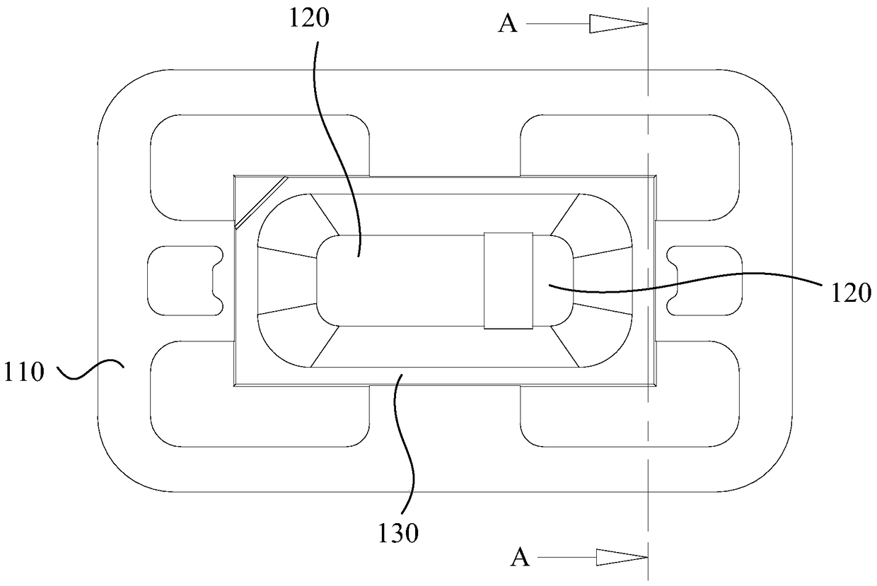
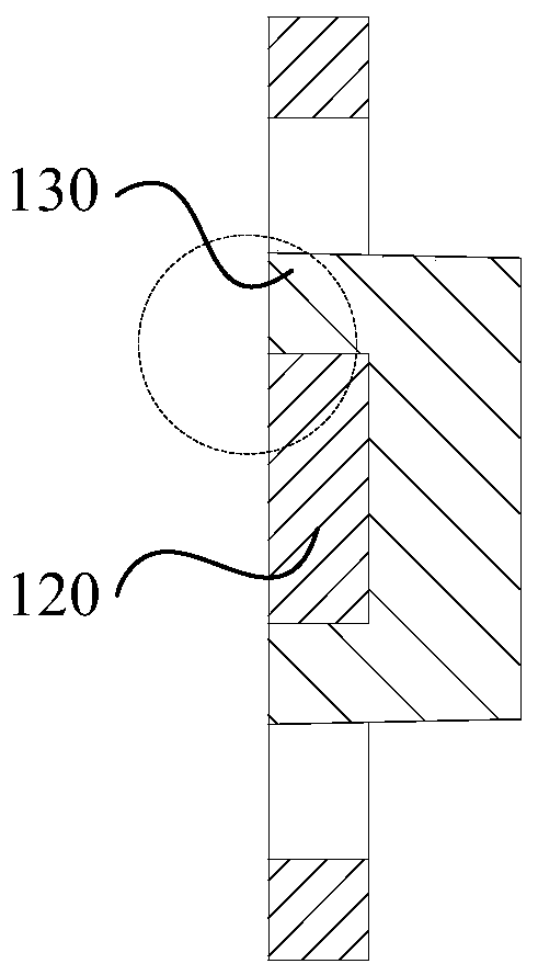
[0004] Based on this, it is necessary to provide an LED bracket and its production method for the problem of poor appearance caused by overflow of glue when forming the insulating body of the LED bracket, which can weaken the phenomenon of glue overflow and ensure the appearance yield of the product

Method used


Image

  • LED bracket and production method thereof
  • LED bracket and production method thereof
  • LED bracket and production method thereof

Examples


Embodiment Construction

[0026] Such as Figure 4 and Figure 5 As shown, the LED bracket provided by the present invention includes an insulating body 230 and at least one pair of conductive terminals 220 combined with the insulating body 230 . Specifically, in this embodiment, the conductive terminals 220 are a pair. It can be understood that in other embodiments, the number of the conductive terminals 220 can be adjusted according to different needs. The conductive terminal 220 serves as the carrier of the LED chip and is electrically connected to the LED chip at the same time. The conductive terminal 220 is then connected to an external power source, so that the LED chip can emit light and work normally.

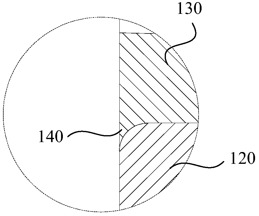
[0027] The insulating body 230 is generally combined with the conductive terminal 220 by injection molding to form an integral structure. Also refer to Figure 6 , the conductive terminal 220 has a bonding surface 223 that is punched and combined with the insulating body 230 and a non-bonding...


PUM


Abstract

The present invention relates to an LED stent which comprises an insulation body and at least one pair of conductive terminals which are combined with the insulation body. Each of the conductive terminals has a non-binding surface which is formed by punching and is adjacent to the binding surface and non-binding surface of the insulation body. An edge arc is formed between the binding surface and the non-binding surface in the punching process. The arc length of the edge arc is 0.03mm to 0.06mm. The invention relates to the production method of the LED stent. According to the LED stent and the production method, the tensile stress borne by a material belt in the punching process is reduced through the mode of stepwise punching, thus the arc length of the edge arc between the binding surface and the non-binding surface is reduced, thus the phenomenon of glue overflow caused by the gap generated by an over large edge arc in forming the insulation body is avoided, and the problem of poor appearance of the LED stent is solved.

Description

technical field [0001] The invention relates to the field of LEDs, in particular to an LED bracket used when packaging LED chips, and a production method of the LED bracket. Background technique [0002] As a new light source, LED has been widely used in lighting, backlight, signal display and other fields. Before the LED terminal application, the LED chip needs to be packaged. Generally, the LED packaging structure includes an LED bracket for carrying LED chips, and an encapsulation glue covering the LED chips. According to different application requirements, phosphor powder may be mixed in the encapsulant to provide light of different colors. The LED bracket usually includes an insulating body and a conductive terminal integrally formed in the insulating body, and generally the conductive terminal is formed first, and then the insulating body is formed on the conductive terminal by means of injection molding, and the conductive terminal is partially exposed during moldin...

Claims


Application Information

Patent Timeline
Patent Type & Authority Patents(China)
IPC IPC(8): H01L33/62H01L33/00F21Y115/10
CPCH01L33/005H01L33/62H01L2933/0066
Inventor 张永林孙业民潘武灵陈文菁刘泽
Owner 东莞智昊光电科技有限公司
Why Eureka
Eureka Blog
Learn More