
Hybrid direct current transmission topological system

A hybrid DC power transmission and topology technology, applied in power transmission AC network and other directions, can solve the problems of high loss and high cost of flexible DC

Active Publication Date: 2016-01-20
ELECTRIC POWER RESEARCH INSTITUTE, CHINA SOUTHERN POWER GRID CO LTD
View PDF3 Cites 3 Cited by
  • Summary
  • Abstract
  • Description
  • Claims
  • Application Information

AI Technical Summary

Problems solved by technology

The primary equipment of the flexible DC end of the traditional hybrid DC transmission topology is designed using the principle of the flexible DC transmission system, so it still has the disadvantages of high cost of flexible DC and relatively high loss

Method used


Image

  • Hybrid direct current transmission topological system
  • Hybrid direct current transmission topological system
  • Hybrid direct current transmission topological system

Examples


Embodiment Construction

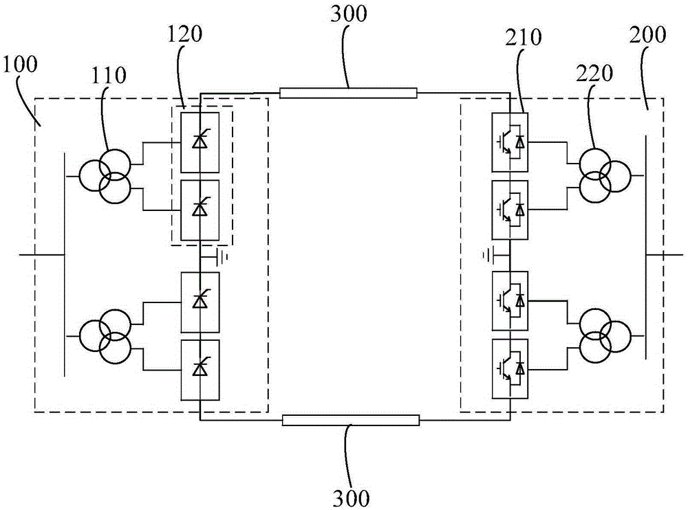
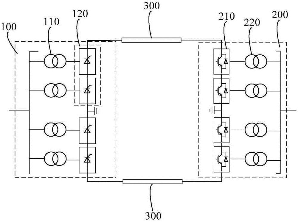
[0017] A hybrid DC transmission topology system such as figure 1 As shown, it includes a rectification-side converter station 100 and an inverter-side converter station 200 connected to the rectification-side converter station 100 .

[0018] The rectification-side converter station 100 includes a rectification-side converter transformer 110 and a grid-commutated converter 120 , and the grid-commutated converter 120 is connected to the rectification-side converter transformer 110 and the inverter-side converter station 200 . The converter transformer 110 on the rectification side is connected to the AC power for transformation processing and then output to the grid commutation converter 120. The grid commutation converter 120 rectifies the transformed AC power to obtain DC power and transmits it to the inverter side converter station 200.

[0019] The inverter-side converter station 200 includes a modular multilevel converter 210 adopting a full-bridge sub-module topology or a...


PUM


Abstract

The invention relates to a hybrid direct current transmission topological system, including a rectification side converter station and an inversion side converter station connected with the rectification side converter station. The rectification side converter station comprises a rectification side converter transformer and a power grid commutation transverter. The inversion side converter station comprises a modular multi-level transverter and an inversion side commutation transverter, wherein the modular multi-level transverter adopts a full bridge submodule topology or a hybrid of the full bridge submodule topology and a half bridge submodule topology, and the inversion side commutation transverter is connected with the modular multi-level transverter. The hybrid direct current transmission topological system can replace an inversion side power grid commutation transverter with the modular multi-level transverter which adopts the full bridge submodule topology or the hybrid of the full bridge submodule topology and the half bridge submodule topology on the basis of a traditional direct current transmission system, and reconstructs the traditional direct current transmission system into a flexible direct current converter station, thereby forming a hybrid direct current topology. By means of reconstruction on the basis of the traditional direct current transmission system, traditional direct current transmission primary equipment at a reconstructed end can be fully utilized, the number of external purchasing equipment is reduced, the reconstruction period is shortened, and the cost is lowered.

Description

technical field [0001] The invention relates to the technical field of direct current transmission systems, in particular to a hybrid direct current transmission topology system. Background technique [0002] At present, the HVDC transmission system mainly includes the traditional HVDC transmission system based on grid commutation technology (LCC-HVDC) and the flexible HVDC transmission system based on voltage source converter (VSC-HVDC). The traditional DC transmission system has large transmission capacity and low cost, but it has disadvantages such as easy commutation failure on the inverter side and strong dependence on the AC system. The flexible DC transmission system can independently adjust active power and reactive power, and has superior controllability and flexibility. It can effectively solve the problems of relatively insufficient local power support and weak voltage stability of the receiving end grid. However, the cost of flexible DC is relatively high. , and...

Claims


Application Information

Patent Timeline
Patent Type & Authority Applications(China)
IPC IPC(8): H02J3/36
CPCY02E60/60
Inventor 黄伟煌李明黎小林黄莹饶宏李岩许树楷刘涛寻斌斌李婧靓田凌钟澎
Owner ELECTRIC POWER RESEARCH INSTITUTE, CHINA SOUTHERN POWER GRID CO LTD
Learn More