Internal structure of wheel housing

A technology for wheel covers and structures, applied to superstructures, superstructure subassemblies, vehicle parts, etc., can solve problems such as differences, and achieve the effect of ensuring rigidity and high rigidity

Active Publication Date: 2017-10-31
MITSUBISHI MOTORS CORP +1
View PDF1 Cites 0 Cited by
  • Summary
  • Abstract
  • Description
  • Claims
  • Application Information

AI Technical Summary

Problems solved by technology

[0006] However, in the case of changing the outer shape of the entire one side of the wheel house inner, the joint position between the wheel house inner and the floor has a large difference from the position in the original wheel house inner

Method used


Image

  • Internal structure of wheel housing
  • Internal structure of wheel housing
  • Internal structure of wheel housing

Examples


Embodiment Construction

[0036] In the following, according to the Figure 1 to Figure 4 The embodiments shown in , describe the invention.

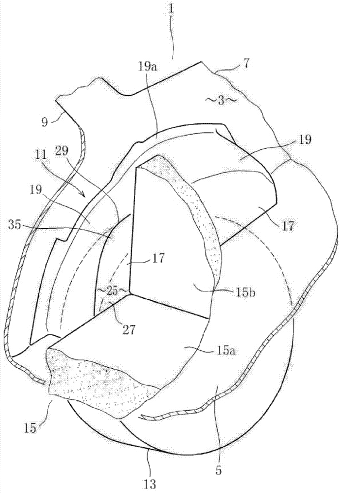
[0037] figure 1 The rear side of a vehicle (for example, a van) to which the invention is applied is shown.

[0038] Referring to the main structure of the truck, in figure 1 The number 1 in the figure is the body of the truck (vehicle), the number 3 is the interior of the compartment formed inside the body 1, the number 5 is the floor for forming the rear floor of the interior 3 of the compartment, and the number 7 is the floor for forming the body The rear quarter inner panel of the inner wall of the compartment of 1, and numeral 9 is the rear pillar inner panel (element for forming the rear panel) formed on the upper part of the rear quarter inner panel 7. The lower part of the rear quarter inner panel 7 has a rear wheel house inner part 11 (wheel house inner part). The rear tire 13 is accommodated inside this rear wheelhouse inner part 11 . Furthermore,...


PUM


Abstract

The invention discloses an internal structure body of a wheel cover. The wheel house inner part, the longitudinal wall and the protruding transverse wall and arranged in the vehicle front-rear direction; the joining part, formed at the longitudinal wall and the lower end of the transverse wall; Part of the transverse wall is recessed outside the vehicle compartment, and the recessed parts include: the first edge line, which retracts from the intersection between the longitudinal wall and the transverse wall to the compartment exterior and extends to one end of the inner part of the wheel house; the second edge line, which retracts from the joint part The outdoor position of the car return is located on the side wall part immediately above the joint part and extends from the end of the first edge line along the joint part; the recessed wall part occupies the recessed area of ​​the recessed part and has a convex surface on the upper part of the recessed wall part toward the interior of the car compartment. A curved surface portion and a second curved surface portion convex below the concave wall portion toward the exterior of the vehicle compartment form the concave wall portion, the first and second curved portions forming first and second edge lines, respectively.

Description

technical field [0001] The present invention relates to a wheel house inner structure in which a recessed part is formed in the wheel house inner part. Background technique [0002] In an automobile (vehicle), such as a van, which includes a rear seat, for example, a second seat behind the front seat (first seat), the rear seat is usually positioned adjacent to the rear wheelhouse interior. [0003] Vehicles need to maximize the space inside the vehicle cabin. Therefore, it is conceived to increase the seat width of the rear seat and expand the space in the vehicle interior. [0004] For this reason, it is conceived to form a recessed part that is recessed outside the vehicle compartment in front of the rear wheel house inner part in the front-rear direction of the vehicle, and is configured to provide the rear seat inside this recessed part and make the rear seat The side portion is closest to the inner surface of the cabin. Of course, the recessed part is recessed in a ...

Claims


Application Information

Patent Timeline
Patent Type & Authority Patents(China)
IPC IPC(8): B62D25/18
Inventor 安藤一今村伊佐博松永聪志
Owner MITSUBISHI MOTORS CORP
Why Eureka
Try Eureka