Cabinet system

A cabinet and installation gap technology, which is applied in the direction of the cabinet/cabinet/drawer parts, rack/frame structure, electrical equipment shell/cabinet/drawer, etc., can solve the lack of support strength/structural rigidity of the overall cabinet frame, The lack of structural strength and rigidity, the influence of the overall cabinet wiring, etc., to achieve the effect of optimizing the space layout, compact structure, convenient and flexible installation

Pending Publication Date: 2018-06-22
ZHEJIANG SHIP ELECTRONICS TECH
View PDF11 Cites 1 Cited by
  • Summary
  • Abstract
  • Description
  • Claims
  • Application Information

AI Technical Summary

Problems solved by technology

[0003] In the prior art, the frame structure of the cabinet is simple in design, and is generally assembled directly from thinner profiles. The assembled profiles between the top frame, the bottom frame and the columns mostly adopt the plug-in connection method, for example, the profiles are directly connected to each other. Inserting, or connecting the top frame, the bottom frame and the columns through a tee structure, so that a beam structure must be installed between the columns to ensure the support strength of the overall cabinet frame, even if the cabinet frame is assembled with beams, due to its The limitations of plug-in or splicing connection methods, the support strength / structural rigidity of the overall cabinet frame are still lacking, and there will be a certain degree of shaking after external force is applied
On the other hand, the existing column structure design is simple and thin, and the structural strength and rigidity are lacking. After the beam is installed in the middle of the side of the cabinet, it will also affect the wiring of the overall cabinet, and the beam will also interfere with the installation of the wiring structure. layout, blocking device access

Method used


Image

  • Cabinet system
  • Cabinet system
  • Cabinet system

Examples


Embodiment Construction

[0025] The following are specific embodiments of the present invention and in conjunction with the accompanying drawings, the technical solutions of the present invention are further described, but the present invention is not limited to these embodiments.

[0026] Combine below Figure 1 to Figure 5 The technical solution provided by the present invention is described in more detail.

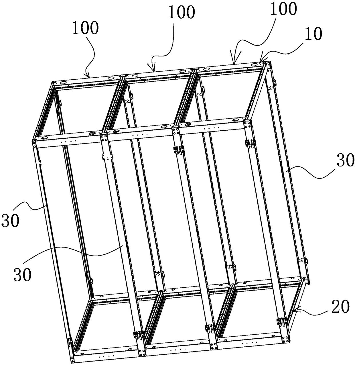
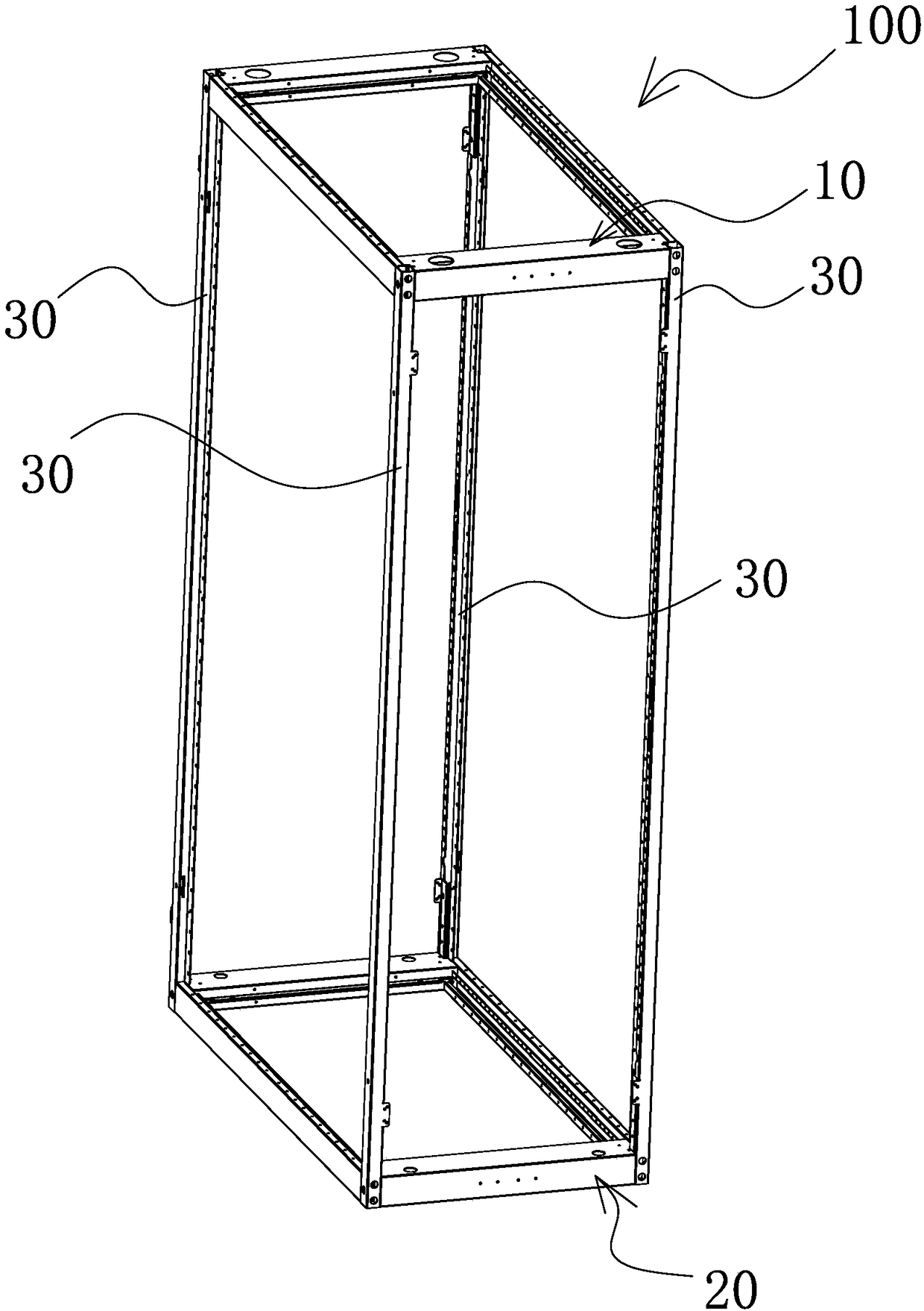
[0027] Such as Figure 1 to Figure 5 As shown, the cabinet system includes at least one cabinet 100, and the cabinet 100 includes:

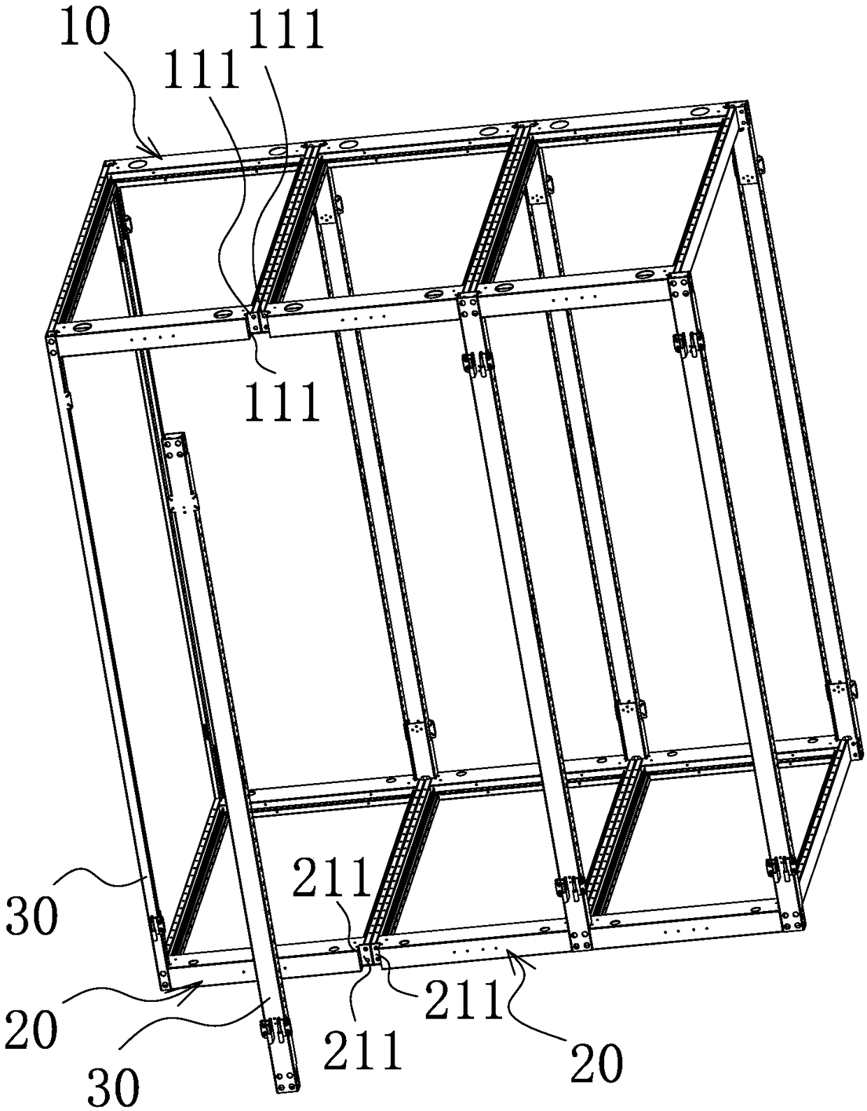
[0028] The top frame 10 is provided with a first installation notch 11 at its corners, and the first installation notch 11 has two first installation surfaces 111 connected to the top frame 10;

[0029] The bottom frame 20 has second installation notches 21 at its corners, and the second installation notches 21 correspond to the first installation notches 11 one by one, and the second installation notches 21 have two the second mounting surface 211;

[0030] U...


PUM


Abstract

The invention provides a cabinet system, which comprises at least one cabinet. The said cabinet comprises a top frame having first mounting notches at corners thereof respectively, and two first mounting surfaces which contact with the top frame is provided on the first mounting notches; a bottom frame having second mounting notches at corners thereof respectively, and the second mounting notcheswhich have two second mounting surfaces contacting with the bottom frame correspond to the first mounting notches one to one; upright posts for connecting the top frame and the bottom frame, and the said upright posts correspond to the first mounting notches one to one, the shape of the upright post installation position fits each mounting notch. A upright post is arranged between each first mounting notch and the corresponding second mounting notch, at this time, the upright posts are respectively and correspondingly connected with the corresponding first mounting surface and the corresponding second mounting surface. The cabinet system in the invention has the advantages of good overall strength and rigidity of the cabinet frame and convenient and flexible wiring installation.

Description

technical field [0001] The invention belongs to the technical field of cabinets and relates to a cabinet system. Background technique [0002] With the rapid development of digital construction, the cabinet system is a cabinet device composed of cabinets, which is widely used in communication, network data processing and other fields, and is an important data communication processing device. [0003] In the prior art, the frame structure of the cabinet is simple in design, and is generally assembled directly from thinner profiles. The assembled profiles between the top frame, the bottom frame and the columns mostly adopt the plug-in connection method, for example, the profiles are directly connected to each other. Plug in, or connect the top frame, bottom frame and column through a tee structure, so that a beam structure must be installed between the columns to ensure the support strength of the overall cabinet frame, even if the cabinet frame is assembled with beams, due to...

Claims


Application Information

Patent Timeline
Patent Type & Authority Applications(China)
IPC IPC(8): H05K5/02H05K7/18
CPCH05K5/0217H05K7/18
Inventor 李永平罗先伟
Owner ZHEJIANG SHIP ELECTRONICS TECH
Why Eureka
Try Eureka