Clamping head for splitting machine

A technology of slitting machine and collet, which is applied in the direction of winding strips, thin material processing, transportation and packaging, etc., which can solve the problem that the collet cannot provide clamping force.

Inactive Publication Date: 2016-01-27
WUXI JIAMEIDA RUBBER & PLASTIC EQUIP
View PDF0 Cites 4 Cited by
  • Summary
  • Abstract
  • Description
  • Claims
  • Application Information

AI Technical Summary

Problems solved by technology

[0003] The purpose of the present invention is to provide a slitting machine chuck to solve the problem that the traditional chuck cannot provide suitable clamping force

Method used


Image

  • Clamping head for splitting machine

Examples


Embodiment Construction

[0018] The present invention will be further described in detail below in conjunction with the accompanying drawings and embodiments. It should be understood that the specific embodiments described here are only used to explain the present invention, but not to limit the present invention. In addition, it should be noted that, for the convenience of description, only some structures related to the present invention are shown in the drawings but not all structures.

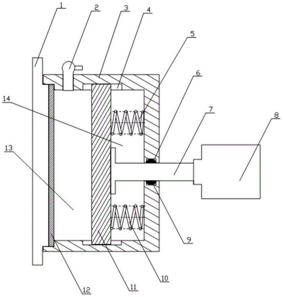
[0019] to combine figure 1 The slitting machine chuck of the present invention will be described in detail.

[0020] The chuck of the slitting machine of the present invention includes a box body 3, and also includes an air valve 2, a chute 4, a first spring 5, a push rod 7, a support member 8, a second spring 10, a pressure plate 11, and a first chamber 13 and the second chamber 14; the upper top plate and the lower bottom plate of the box body 3 are concavely provided with chute 4, the pressure plate 11 is clam...


PUM


Abstract

The invention relates to the technical field of clamps, in particular to a clamping head for a splitting machine. The clamping head for the splitting machine comprises a box body and further comprises an air valve, chutes, a first spring, an ejector rod, a support part, a second spring, a pressing plate, a first cavity and a second cavity. An upper top plate and a lower bottom plate of the box body are concavely provided with the chutes. The pressing plate is clamped into the chutes. The ejector rod is arranged in the side wall of the box body in a penetrating mode and stretches into one end in the box body to be fixed onto the pressing plate. One end, extending outside the box body, of the ejector rod is provided with a support part in a rotary mode. The box body is divided by the pressing plate into the first cavity and the second cavity. The first spring and the second spring are extruded into the second cavity by means of the pressing plate. The air valve is arranged to a top plate of the first cavity in a penetrating mode. Gas is injected into the first cavity. Proper clamping force can be provided by gas and springs due to flexibility.

Description

technical field [0001] The invention relates to the technical field of clamps, in particular to a chuck of a slitting machine. Background technique [0002] At present, the unwinding of the slitting machine is generally tightened with an inflatable chuck. The working principle of the inflatable chuck is: input the compressed air into the internal air bag of the chuck, and transmit the force raised by the air bag to the key block, so that the key blocks evenly distributed around the circumference expand outward, and tighten the inner diameter of the paper tube to achieve tightening. Purpose. The disadvantage of this chuck is that the expansion force is closely related to the compressed air force and the operator's operation process, and the clamping force is closely related to objective factors and human subjective factors, so it is difficult to accurately control to provide a suitable clamping force. Contents of the invention [0003] The purpose of the present invention...

Claims


Application Information

Patent Timeline
Patent Type & Authority Applications(China)
IPC IPC(8): B65H16/02
Inventor 张芳芳
Owner WUXI JIAMEIDA RUBBER & PLASTIC EQUIP
Why Eureka
Try Eureka