Woodworking machining center

A processing center and woodworking technology, applied in wood processing equipment, manufacturing tools, multi-purpose machinery, etc., can solve problems such as poor stability, achieve the effects of ensuring stability, reducing driving parts, and improving positioning stability

Pending Publication Date: 2020-11-20
吴善旺
View PDF2 Cites 3 Cited by
  • Summary
  • Abstract
  • Description
  • Claims
  • Application Information

AI Technical Summary

Problems solved by technology

[0005] The purpose of the present invention is to solve the above problems in the existing technology, and propose a woodworking processing center to solve the problem of poor stability of synchronous pressing and positioning of multiple workpieces in the existing woodworking processing center

Method used


Image

  • Woodworking machining center
  • Woodworking machining center
  • Woodworking machining center

Examples


Embodiment 1

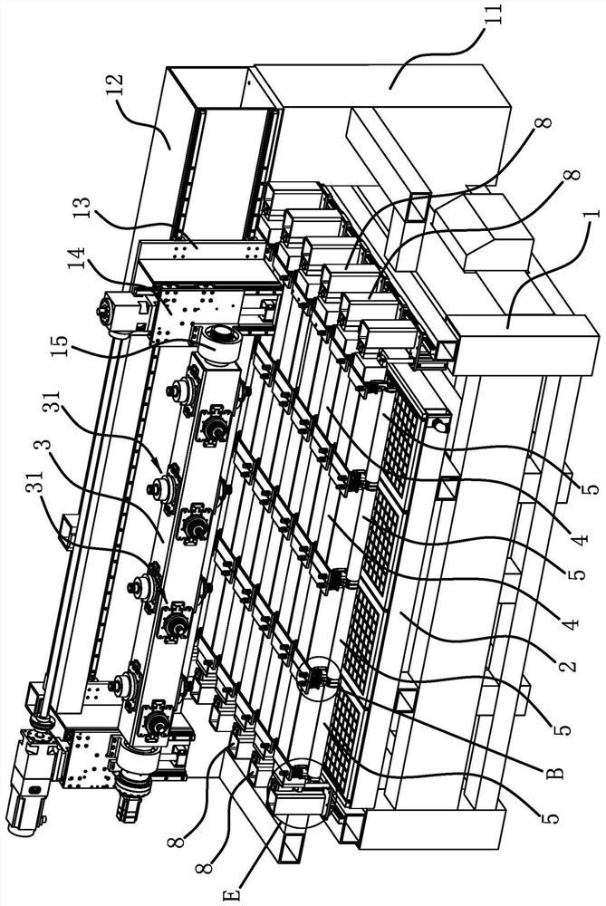
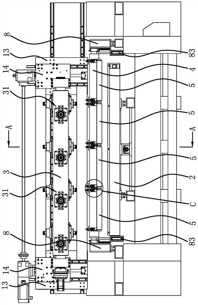
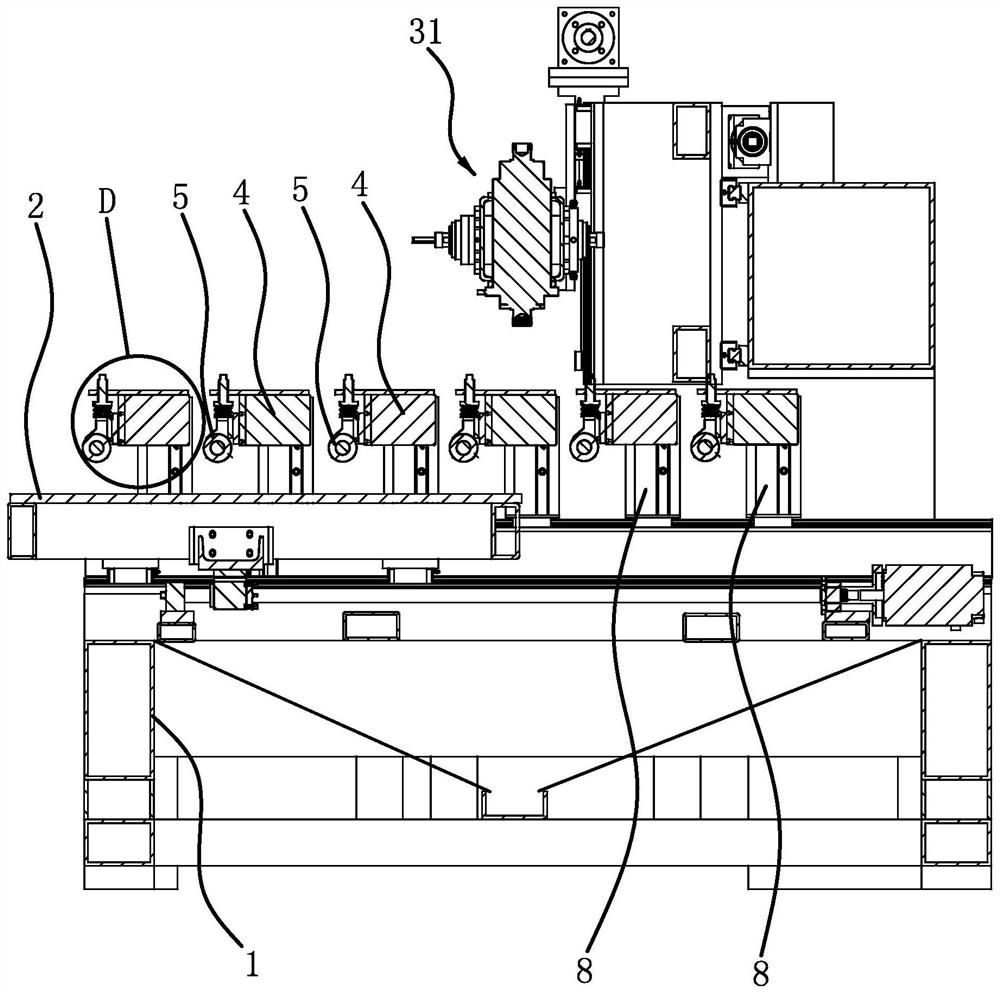
[0035] Such as figure 1 , figure 2 , image 3 As shown, a woodworking processing center includes a frame 1, a tool rack 3 and a processing platform 2. The frame 1 has two vertical columns 11, and a crossbeam 12 arranged horizontally is fixed between the tops of the two columns 11. On the crossbeam 12, two horizontal carriages 13 are slidingly connected in the horizontal direction, and the vertical carriages 14 are slidingly connected in the vertical direction on the two horizontal carriages 13, and supports 15 are fixed on the sides of the two vertical carriages 14. , the tool holder 3 is in the shape of a strip, and the two ends of the tool holder 3 are respectively rotatably connected to the two supports 15, so that the tool holder 3 is arranged laterally, and the tool holder 3 is provided with a number of processing components 31 along the length direction. Component 31 then comprises the processing motor that is fixed on the tool holder 3 and the cutter that is installe...

Embodiment 2

[0039] The structure of this woodworking processing center is basically the same as that of Embodiment 1, the difference is that Figure 9 , Figure 10 As shown, the pressure roller 5 is connected on the lifting frame 4 through an elastic member, the two ends of the rotating shaft 51 of the pressing roller 5 are provided with connecting sleeves 53, the bearing 65 is arranged between the connecting sleeve 53 and the rotating shaft 51, and the connecting parts include springs. The steel wire 9 and the fixed ring 10, the fixed ring 10 is sleeved on the lifting frame 4 and locked and fixed on the lifting frame 4 by a plurality of bolts 101 penetrating in the radial direction, the spring steel wire 9 includes a fixed section 91, an elastic section 92 and a connection Section 93, fixed section 91 and connecting section 93 are all in a spiral shape, and elastic section 92 is located between fixed section 91 and connecting section 93. 93 helical sleeve is set on the connecting sleeve...

Embodiment 3

[0041] The structure of this woodworking processing center is basically the same as that of Embodiment 1. The difference is that the elastic member includes two elastic cylinders. It is connected with the connecting frames 6 at both ends of the pressure roller 5 .


PUM


Abstract

The invention provides a woodworking machining center, and belongs to the technical field of mechanical equipment. The woodworking machining center solves the problem that an existing woodworking machining center is poor in stability of synchronously pressing and positioning a plurality of workpieces. The woodworking machining center comprises a rack and a machining platform horizontally arrangedon the rack, the rack is connected with a lifting frame capable of ascending and descending, the lifting frame is in a long strip shape and is arranged above the machining platform, the lifting frameis connected with a plurality of pressing rollers, the pressing rollers are sequentially arranged in the length direction of the lifting frame, and the lower portions of the pressing rollers are lowerthan the lower portion of the lifting frame; the multiple pressing rollers can independently ascend and descend relative to the lifting frame, and elastic pieces capable of enabling the pressing rollers to have the downward movement trend are arranged between the multiple pressing rollers and the lifting frame. The woodworking machining center is good in stability of synchronously pressing and positioning a plurality of workpieces.

Description

technical field [0001] The invention belongs to the technical field of mechanical equipment and relates to a woodworking processing center. Background technique [0002] The woodworking processing center integrates a variety of wood processing methods. The typical one is used for engraving. From the processing principle, it is a combination of drilling and milling. It has a wide range of applications, including woodworking engraving machines, laser engraving machines, advertising engraving machines, jade Engraving machine, stone engraving machine, cylinder engraving machine, etc., engraving machine has a wide range of applications, and even replaces manual engraving technology, laying the foundation for mass and rapid production of products. The woodworking processing center is equipped with a processing platform and processing components. In order to improve processing efficiency, multiple workpieces will be placed on the processing platform for simultaneous processing, and...

Claims


Application Information

Patent Timeline
Patent Type & Authority Applications(China)
IPC IPC(8): B27C9/04
CPCB27C9/04
Inventor 吴善旺
Owner 吴善旺
Why Eureka
Try Eureka