A fan shutter device

A shutter device, fan technology, applied in pump devices, windows/doors, special equipment for doors/windows, etc., can solve problems such as increasing the resistance of blade opening, frame deformation, and flow field instability.

Inactive Publication Date: 2017-04-19
ASIA VITAL COMPONENTS SHENZHEN CO LTD
View PDF4 Cites 0 Cited by
  • Summary
  • Abstract
  • Description
  • Claims
  • Application Information

AI Technical Summary

Problems solved by technology

[0005] A general axial flow fan includes a fan frame and a fan wheel, the fan wheel is pivotally connected in the fan frame, and when the axial flow fan is in operation, the fan wheel rotates forward in the fan frame to turn the fan wheel The air from one side is sent to the other side to dissipate heat from the environment and heating elements on the other side. The fans are often used in system equipment such as personal computers and servers to dissipate the heat generated by the electronic components inside the system. It is derived from the inside of the system; however, this type of fan often encounters the problem of airflow backflow in applications, that is, when the fan fails or is not working, the external airflow flows back into the system through the fan, causing the flow field in the system to become unstable ; In view of the problem of fan airflow backflow, many companies have developed a variety of airflow non-return devices. At present, there are common windshield structures similar to louvers. For example, the case of Chinese Patent No. 200620145328.3 discloses a cooling fan, which includes a fan The main body is equipped with louvers on the side of the air outlet of the fan body. The louvers include a frame and multiple louver blades, and the two ends of the louver blades protrude from the shaft holes on the frame. When the blades are opened, the blades droop due to gravity when they stop rotating, and they are positioned through the convex points on the frame when they droop. Frictional interference with the inner wall of the frame increases the resistance of the blades to open, which makes the blades not open smoothly. In addition, the convex points for positioning the frame are set on the inner side of the frame, which requires high mold costs; therefore, the conventional technology has the following disadvantages:
[0008] 3. High mold cost

Method used


Image

  • A fan shutter device
  • A fan shutter device
  • A fan shutter device

Examples


Embodiment Construction

[0045] The above-mentioned purpose of the present invention and its structural and functional characteristics will be described based on the preferred embodiments of the accompanying drawings.

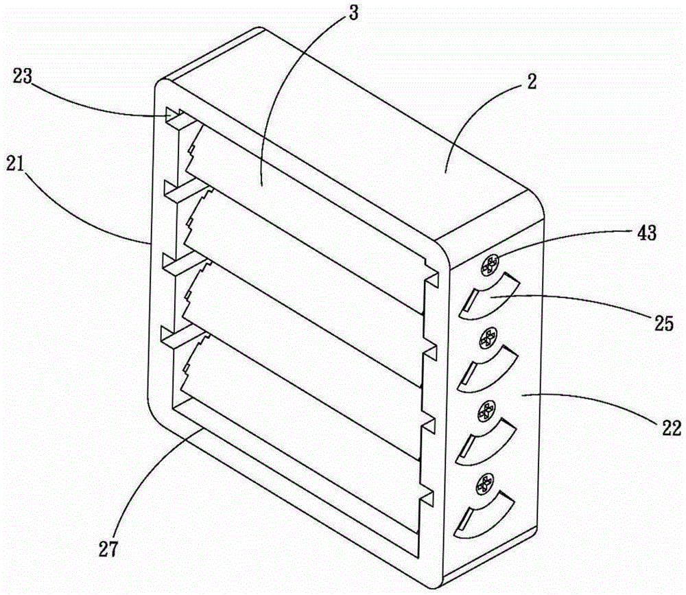
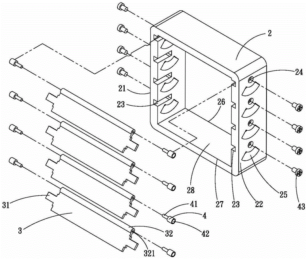
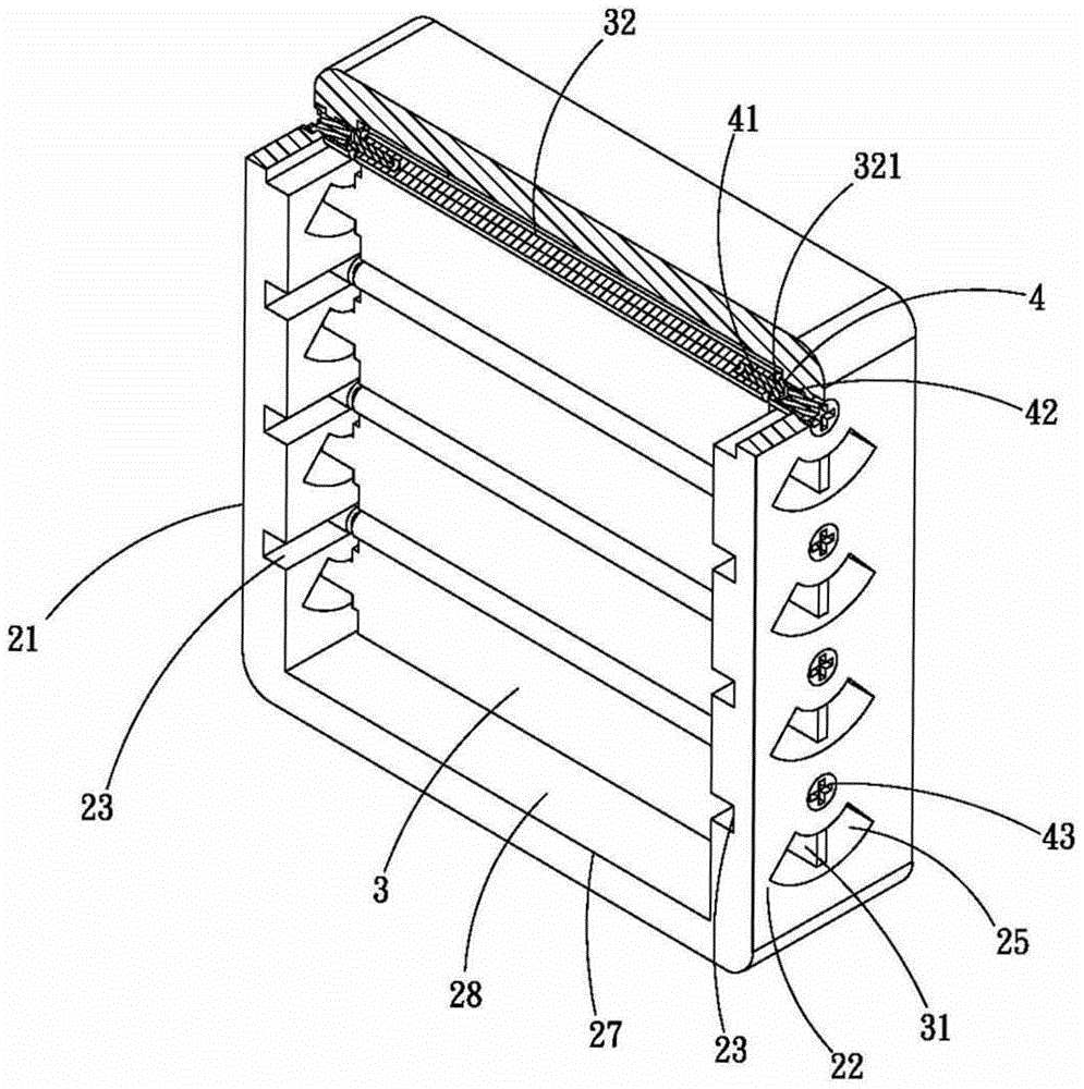
[0046] Such as figure 1 , figure 2 and image 3 As shown, it is a three-dimensional schematic diagram, a three-dimensional exploded schematic diagram and a partial cross-sectional schematic diagram of a preferred embodiment of the present invention. As shown in the figure, the fan shutter device of the present invention includes a frame 2, a plurality of blades 3 and a plurality of bushings 4 .

[0047] The frame 2 has a first frame 21 and a second frame 22, and has an inlet 26 and an outlet 27 on both sides respectively, a channel 28 is arranged between the inlet 26 and the outlet 27, and the first frame 21 On the second frame 22, there are respectively multiple connecting grooves 23, multiple fixing holes 24 and multiple displacement holes 25, and the connecting grooves 23, fixing...


PUM


Abstract

The invention relates to a fan shutter device. The fan shutter device comprises a framework, multiple blades and multiple shaft sleeves. A first frame and a second frame of the framework are respectively provided with multiple combined connecting grooves, multiple fixing holes and multiple displacement holes. Each blade is provided with a spreading part and a connecting shaft. Each connecting shaft is provided with a shaft sleeve in a connecting groove position. Multiple fixing elements are respectively arranged in shaft cylinders through the fixing holes. Accordingly, the rotating clearance is formed between each blade and the frame, the assembly deformation and the friction interference between the blades and the frame can be avoided, and the manufacturing cost is reduced. In addition, spreading parts are arranged in the displacement holes to carry out opening limiting so that opening angles of the blades are facilitated.

Description

[0001] 【Technical field】 [0002] The invention relates to a fan structure, in particular to a fan louver device which can avoid assembly deformation and frictional interference between blades and frames, and can reduce manufacturing costs. [0003] 【Background technique】 [0004] Due to the vigorous development of the electronic product industry today, the performance of electronic components is rapidly improving, and the calculation processing speed is getting faster and faster, and the calculation speed of the internal chipset is constantly increasing, and the number of chips is also increasing, so that the heat emitted by the aforementioned chips during work is also increasing. As the number of chips increases, and the aforementioned heat is not dissipated immediately and quickly, it will greatly affect the performance of electronic components, such as reducing the processing speed of electronic components, crashing, burning, etc., so heat dissipation has become an important...

Claims


Application Information

Patent Timeline
Patent Type & Authority Patents(China)
IPC IPC(8): E06B7/084F04D25/14
Inventor 陈茂琳朱培素傅明鸳
Owner ASIA VITAL COMPONENTS SHENZHEN CO LTD
Why Eureka
Try Eureka