
An electric rotating shaft device for a side-hung door of a shower room

A technology of electric rotating shaft and swing door, applied in door/window accessories, power control mechanism, wing fan parts, etc., can solve the problems of no electric door opening function, no angle arbitrary positioning function, bulky volume, etc., to achieve convenient door opening The effect of arbitrary adjustment of the angle, large torque and simple structure design

Active Publication Date: 2016-05-11
中山市玛莎洁具有限公司
View PDF5 Cites 0 Cited by
  • Summary
  • Abstract
  • Description
  • Claims
  • Application Information

AI Technical Summary

Problems solved by technology

The swing doors of the shower room on the market are all manual. In order to improve people's quality of life, our company has changed the traditional single manual door opening method. The existing ordinary swing door of the shower room is just an ordinary swing door with an angle limit. The shaft does not have the function of electric door opening
Only the large-scale electric floor spring can open the door with this kind of electric shaft. It does not have the function of arbitrary positioning of the angle. Because the volume is too bulky, it is not suitable for the shower room industry, and it is buried under the ground, which is not suitable for the wet shower room. environment use

Method used


Image

  • An electric rotating shaft device for a side-hung door of a shower room
  • An electric rotating shaft device for a side-hung door of a shower room
  • An electric rotating shaft device for a side-hung door of a shower room

Examples


Embodiment Construction

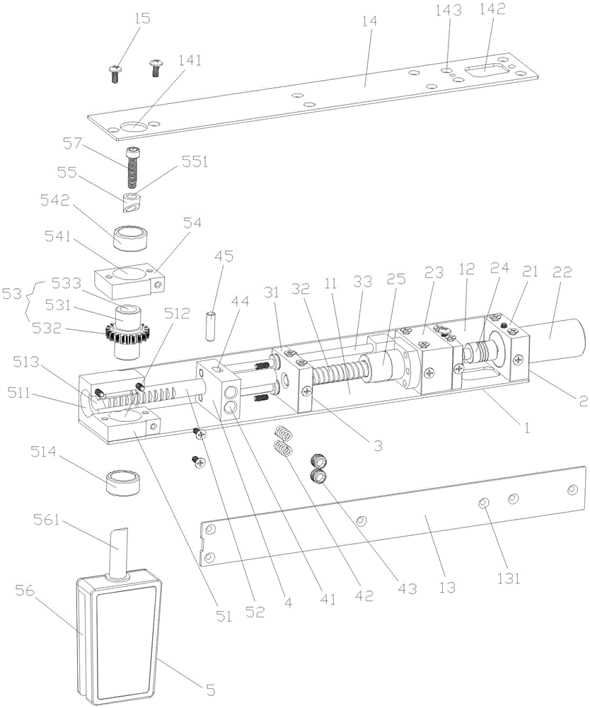
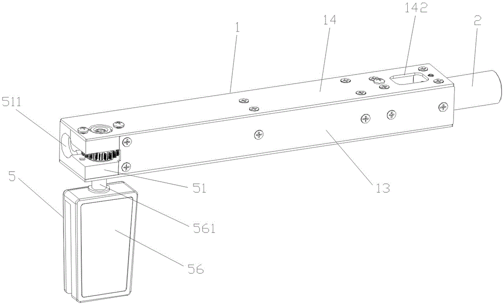
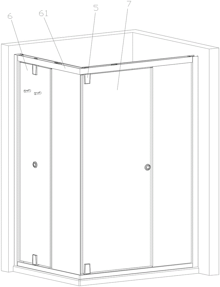
[0018] Such as Figures 1 to 3 As shown, the shower room swing door electric shaft device of the present invention is installed on the top of the door frame 61 of the shower room swing door 6, which includes a mounting frame 1, a driving mechanism 2, a transmission mechanism 3, a clutch body 4 and a gear transmission assembly 5.

[0019] The installation frame 1 has a rectangular parallelepiped structure as a whole, and it is compatible with the top door frame 81 of the side-hung door 8 of the shower room. The front side plate 13 at the front end of the plate 11 and the upper cover plate 14 located at the top of the rear side plate 12 and the front side plate 13, the upper cover plate 14 has the same structure as the lower cover plate 11 and is parallel to each other, the rear side plate 12 The structure is also the same as that of the front side plate 13 and parallel to each other; wherein, one end of the upper cover plate 14 is provided with a circular through hole 141, and ...


PUM


Abstract

The invention relates to an electric rotary shaft device of a side hung door of a shower room. The electric rotary shaft device comprises a mounting frame, a driving mechanism, a transmission mechanism, a clutch body and a gear transmission assembly, and the driving mechanism, the transmission mechanism, the clutch body and the gear transmission assembly are arranged on the mounting frame. The driving mechanism is arranged at one end of the mounting frame, and comprises a motor mounting seat, a driving motor, a coupling, a bearing pedestal and a nut. The transmission mechanism is arranged on the middle segment of the mounting frame and on one side of the driving mechanism and comprises a fixed block, a lead screw and a push rod. The clutch body is located on one side of the fixed block, and is embedded inwards from the front side end, a spring is fixed, and a stirring pin is detachably arranged inwards from the top. The gear transmission assembly is arranged at the other end of the mounting frame and comprises a gear base, a gear rack, a gear, an upper gear fixing plate, a bevel expansion ring and a rotary shaft door clamp. The electric rotary shaft device is simple and reasonable in structural design and convenient to maintain, the door opening angle can be freely adjusted, noise is low, and the electric rotary shaft device is suitable for being used on the shower room, and suitable for being applied and popularized.

Description

technical field [0001] The invention relates to the technical field of a swing door of a shower room, in particular to an electric rotating shaft device for a swing door of a shower room. Background technique [0002] Existing ordinary manual shaft swing doors are already available on the market, and our company has carried out structural innovation on the basis of it to become an electric shaft swing door. The swing doors of the shower room on the market are all manual. In order to improve people's quality of life, our company has changed the traditional single manual door opening method. The existing ordinary swing door of the shower room is just an ordinary swing door with an angle limit. The rotating shaft does not have the function of electric door opening. Only the large-scale electric floor spring can open the door with this kind of electric shaft. It does not have the function of arbitrary positioning of the angle. Because the volume is too bulky, it is not suitable...

Claims


Application Information

Patent Timeline
Patent Type & Authority Patents(China)
IPC IPC(8): E05D7/081E05F15/608
CPCE05D7/081E05Y2900/114E05Y2900/132
Inventor 梁志坚张鹏鹏
Owner 中山市玛莎洁具有限公司
Learn More