Supercharge Your Innovation With Domain-Expert AI Agents!

Engine speed control structure and control method for rear power take-off

A technology of engine speed and control structure, applied in engine control, machine/engine, electrical control, etc., can solve the problems of potential safety hazards, the inability to limit the maximum engine speed, etc., and achieve the effect of ensuring safety

Active Publication Date: 2018-10-16
WEICHAI POWER CO LTD
View PDF7 Cites 0 Cited by
  • Summary
  • Abstract
  • Description
  • Claims
  • Application Information

AI Technical Summary

Problems solved by technology

[0004] However, neither of these two methods can limit the maximum speed of the engine at the time of power take-off. Therefore, the above two methods of controlling the speed of the engine at the time of power take-off may have certain potential safety hazards.

Method used


Image

  • Engine speed control structure and control method for rear power take-off
  • Engine speed control structure and control method for rear power take-off
  • Engine speed control structure and control method for rear power take-off

Examples


Embodiment 1

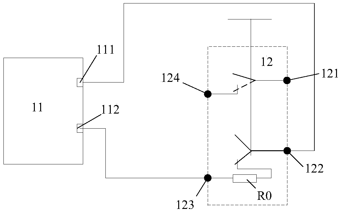
[0043] figure 1 It is a structural schematic diagram of the engine speed control structure at the time of power take-off provided in Embodiment 1 of the present invention. Such as figure 1 As shown, the control structure includes:

[0044] ECU 11 and rear power take-off switch 12, wherein, ECU comprises first interface 111 and second interface 112, and rear power take-off switch 12 comprises first contact 121, second contact 122, third contact 123, fourth contact Point 124 and preset resistor R0;

[0045] The preset resistor R0 is set on the line where the third contact 123 is located;

[0046] The first contact 121 is connected to a power supply ( figure 1 Not shown in ) connection, the power supply can be a storage electric screen that provides 24V voltage.

[0047] The first interface 111 is connected to the second contact 122;

[0048] The fourth contact 124 is used to connect the rear power take-off device ( figure 1 not shown in);

[0049] The second interface 11...

Embodiment 2

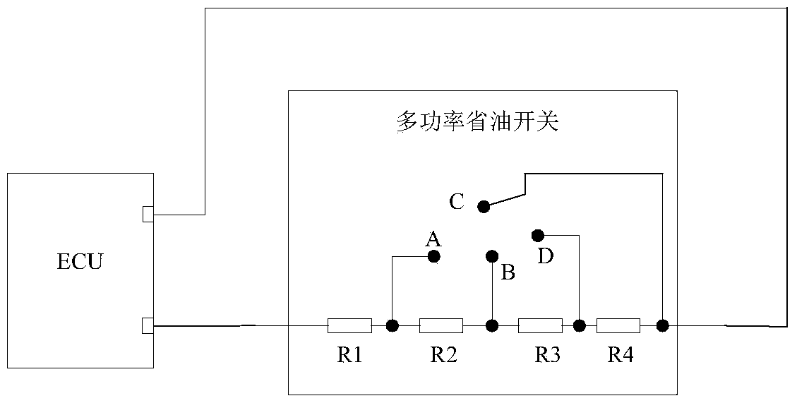
[0069] Figure 4 It is a structural schematic diagram of the engine speed control structure at the time of power take-off provided by Embodiment 2 of the present invention. It should be noted, Figure 4 The shown engine speed control structure at the time of power take-off includes all components of the control structure in Embodiment 1, and the connection relationship of each component is the same as that of the corresponding components in Embodiment 1.

[0070] specifically, Figure 4 The engine speed control structure when the shown rear power take-off includes an ECU 41 and a rear power take-off switch 42, wherein the ECU 41 includes a first interface 411 and a second interface 412, and the rear power take-off switch 42 includes a first contact 421, a second contact The point 422, the third contact 423, the fourth contact 424 and the preset resistor R0'.

[0071] The preset resistor R0' is set on the line where the third contact 423 is located;

[0072] The first conta...


PUM


Abstract

The invention provides an engine rotation speed control structure and a control method thereof during rear power take-off. The control structure comprises an electronic control unit (ECU) and a rear power take-off switch. The ECU comprises a first port and a second port. The rear power take-off switch comprises a first contactor, a second contactor, a third contactor, a fourth contactor and a preset resistor. The preset resistor is arranged on the circuit where the third contactor is located. The first contactor is connected with a power source capable of supplying power. The first port is connected with the second contactor. The fourth contactor is used for switching on a rear power take-off device. The second port is connected with the third contactor. When the rear power take-off switch is switched off, the second contactor is communicated with the third contactor, and the first contactor is communicated with the fourth contactor. According to the engine rotation speed control structure and the control method thereof, the maximum rotation speed of an engine does not exceed a rotation speed threshold value during rear power take-off, and accordingly the safety during rear power take-off is ensured.

Description

technical field [0001] The invention relates to the field of vehicle engine control, in particular to an engine rotation speed control structure and a control method thereof during rear power take-off. Background technique [0002] When the vehicle is parked to take power, in order to meet the requirements of the rear power take-off device for the engine speed and ensure the safety of the rear power take-off, the engine speed is required not to be too high. Therefore, when the vehicle is parked to take power, it is necessary to control engine speed. For example, the maximum speed of a diesel engine can reach more than 2500rpm, but in the actual application of the rear power take-off device, such a high speed is not required, and an excessively high speed may cause potential safety hazards. In order to meet the requirements of safety performance, it is required that the speed of the engine should be less than or equal to 1500rmp when the rear power take-off vehicle is parked...

Claims


Application Information

Patent Timeline
Patent Type & Authority Patents(China)
IPC IPC(8): F02D41/00
Inventor 刘成龙陈玉杰李同楠
Owner WEICHAI POWER CO LTD
Features
  • R&D
  • Intellectual Property
  • Life Sciences
  • Materials
  • Tech Scout
  • Unparalleled Data Quality
  • Higher Quality Content
  • 60% Fewer Hallucinations
Learn More