Bolt type sucker

A bolt type, suction cup technology, applied in suction cups, connecting components, mechanical equipment, etc., can solve the problems of no longer adsorption, prone to air leakage, suction cup body leakage, etc., to achieve permanent adsorption, prevent air leakage, Avoid the effect of laxity

Inactive Publication Date: 2016-01-27
江苏南田工机有限公司
View PDF1 Cites 4 Cited by
  • Summary
  • Abstract
  • Description
  • Claims
  • Application Information

AI Technical Summary

Problems solved by technology

[0002] At present, the suction cup used for hanging items on the market is generally a soft disc-shaped suction cup body, which is pressed on the wall, glass or other planes during use, and the air in the suction cup body is removed to form a vacuum state. Under the action, the suction cup body is adsorbed on the plane. Due to the low strength of the suction cup body itself, it is easy to deform after being stressed, and its edge is easy to leak air, which will destroy the vacuum state and no longer have adsorption, which will affect the use. In view of this situation, there are There is also a suction cup with a gland. There is a rod passing through the gland in the middle of the suction cup body. There is a compression wrench on the rod. The edge of the suction cup body prevents the air leakage of the suction cup body, but this kind of suction cup body cannot adjust the pressure of the compression wrench, and cannot ensure that the outer support of the gland is pressed tightly on the edge of the suction cup body
[0003] Patent No. 200820046494.7 discloses a bolt-type suction cup. The gland and the suction cup body are used in conjunction with the grooves provided around the gland and the convex strips under the suction cup body, which is prone to air leakage, resulting in air leakage from the suction cup body. Affect the use effect of the suction cup

Method used


Image

  • Bolt type sucker

Examples


Embodiment Construction

[0012] The implementation of the present invention will be illustrated by specific specific examples below, and those skilled in the art can easily understand other advantages and effects of the present invention from the contents disclosed in this specification.

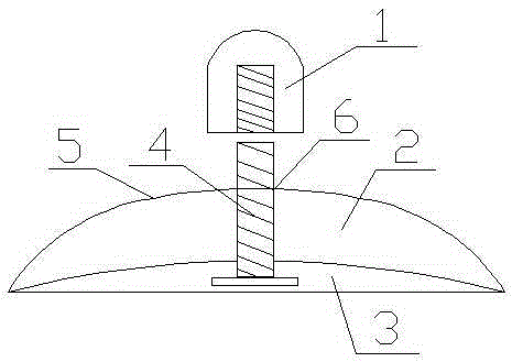
[0013] Such as figure 1 Shown is the structure schematic diagram of the present invention, a kind of bolt-type sucker, comprises flexible sucker body 3, is provided with gland 5 above the sucker body 3, forms a hollow part 2 between the bottom surface of gland 5 and sucker body 3, sucker The middle part of the body 3 is provided with a screw 4, the screw 4 is provided with a compression nut 1, the middle part of the gland 5 is also provided with a through hole 6, the screw 4 passes through the through hole 6 and is arranged in the middle of the suction cup, and the compression nut 1 is arranged in the pressure Cover 5. In the present invention, by setting the compression nut 1 and turning the compression nut 1 duri...


PUM


Abstract

The invention discloses a bolt type sucker. The bolt type sucker is characterized by comprising a flexible sucker body, wherein a gland is arranged on the sucker body; a hollow part is formed between the bottom surface of the gland and the sucker body; and a screw rod is arranged at the middle part of the sucker body, and is provided with a pressing screw cap. The bolt type sucker has the following advantages: as the pressing screw cap is provided, the pressing screw cap can be screwed to adjust the position of the screw rod penetrating through a through hole in use, and the bottom peripheral edge of the gland is pressed on the outer edge of the sucker body; and pressure can be voluntarily adjusted, so that the gland can be tightly pressed on the sucker body to effectively prevent the air leakage phenomenon of the sucker body, and long-time absorption and firm absorption are guaranteed. The gland and the sucker body are formed to an integrated structure, so that the air leakage caused by the contact infirmness of the gland and the sucker body can be effectively prevented to influence the adsorptive property.

Description

technical field [0001] The invention relates to a suction cup, in particular to a bolt type suction cup. Background technique [0002] At present, the suction cup used for hanging items on the market is generally a soft disc-shaped suction cup body, which is pressed on the wall, glass or other planes during use, and the air in the suction cup body is removed to form a vacuum state. Under the action, the suction cup body is adsorbed on the plane. Due to the low strength of the suction cup body itself, it is easy to deform after being stressed, and its edge is easy to leak air, which will destroy the vacuum state and no longer have adsorption, which will affect the use. In view of this situation, there are There is also a suction cup with a gland. There is a rod passing through the gland in the middle of the suction cup body. There is a compression wrench on the rod. The edge of the sucker body prevents the sucker body from leaking, but this sucker body cannot adjust the pres...

Claims


Application Information

Patent Timeline
Patent Type & Authority Applications(China)
IPC IPC(8): F16B47/00
Inventor 成海英
Owner 江苏南田工机有限公司
Why Eureka
Try Eureka