Self-adaptation locking device

A locking device and self-adaptive technology, applied in the direction of brake actuators, etc., can solve the problems of cumbersome operation, complex locking mechanism structure, inability to adapt to the position deviation of the upper body rotating part, etc., and achieve the effect of simple structure requirements and small space

Active Publication Date: 2016-01-27
GUIZHOU AEROSPACE TIANMA ELECTRICAL TECH
View PDF10 Cites 2 Cited by
  • Summary
  • Abstract
  • Description
  • Claims
  • Application Information

AI Technical Summary

Problems solved by technology

[0003] The purpose of the present invention is to provide an adaptive locking device to solve the problem that the traditional locking mechanism is complex in structure, cumbersome in operation, and unable to adapt to the position deviation of the turning part of the bodywork in the azimuth direction, resulting in gaps

Method used


Image

  • Self-adaptation locking device
  • Self-adaptation locking device
  • Self-adaptation locking device

Examples


Embodiment Construction

[0019] The technical scheme of the present invention will be further described below in conjunction with the accompanying drawings, but the required protection scope is not limited to the description;

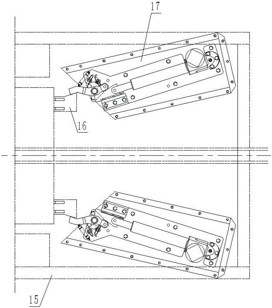
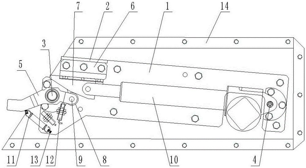
[0020] like Figure 1-2 As shown, the self-adaptive locking device provided by the present invention includes two symmetrically arranged locking mechanisms 17 installed on the support platform 15. The locking mechanism 17 includes a base plate 1, and the left and right ends of the base plate 1 are respectively provided with The rotary shaft A3 and the rotary shaft B4 perpendicular to it, the electric push rod 10 is hinged on the rotary shaft B4, the upper left corner of the bottom plate 1 is provided with a support plate 2, and the pressure plate 6 is installed through the support plate 2, and the electric push rod 10 The end of the telescopic rod is hinged with a slider 7 that matches the pressure plate 6; the rotary shaft A3 is hinged with a locking block 5, and the right end...


PUM


Abstract

The invention discloses a self-adaptation locking device. The self-adaptation locking device comprises two locking mechanisms which are symmetrically installed on a supporting platform. The locking mechanisms comprise bottom plates. The left end and the right end of each bottom plate are provided with a rotating shaft A and a rotating shaft B respectively, wherein the rotating shaft A and the rotating shaft B are perpendicular to the bottom plate. An electric push rod is hinged to each rotating shaft B. A supporting plate is arranged at the upper left corner of each bottom plate. The bottom plates are provided with pressing plates through the supporting plates. A sliding block matched with the corresponding pressing plate is hinged to the tail end of a telescopic rod in each electric push rod. A locking block is hinged to each rotating shaft A. Wheels abutting against the end faces of the sliding blocks are hinged to the right ends of the locking blocks through hinge shafts. The other ends of the locking blocks are bent into shapes matched with the shape of a locking seat of equipment needing to be locked. According to the self-adaptation locking device, a top-mounted rotation part can be automatically locked and unlocked in the azimuth direction in confined space, and the device can adaptive to the position deviation of the top-mounted rotation part.

Description

technical field [0001] The invention relates to the technical field of mechanical design, in particular to an adaptive locking device. Background technique [0002] A certain piece of equipment needs to use a locking mechanism to complete the locking or unlocking action of the turning part of the bodywork. At present, there are many kinds of locking mechanisms, but the structure is complex, the operation is cumbersome, and it cannot adapt to the position deviation of the turning part of the bodywork in the azimuth direction. gap. Contents of the invention [0003] The present invention aims to provide an adaptive locking device to solve the problem that the traditional locking mechanism has a complex structure and cumbersome operation, and cannot adapt to the position deviation of the turning part of the bodywork in the azimuth direction, resulting in gaps. [0004] The present invention is achieved through the following technical solutions: [0005] An adaptive locking ...

Claims


Application Information

Patent Timeline
Patent Type & Authority Applications(China)
IPC IPC(8): F16D65/14
Inventor 张栩田洪军
Owner GUIZHOU AEROSPACE TIANMA ELECTRICAL TECH
Why Eureka
Try Eureka