LED panel light back plate mechanism

A lamp backplane and flat panel technology, which is applied in the field of LED lighting, can solve the problems of material loss, increase rework rate, and damage the luminous effect of flat light source, so as to save the cost of lamps and reduce the defective rate.

Inactive Publication Date: 2016-01-27
CHANGZHOU ADVANCED OPTRONIC DEVICES
View PDF0 Cites 5 Cited by
  • Summary
  • Abstract
  • Description
  • Claims
  • Application Information

AI Technical Summary

Problems solved by technology

The above technical methods have the following disadvantages: 1. The foam is large in size, and it is easy to be contaminated with dust, hair and other fine debris during production and transportation. The flat panel lamp generates a large amount of static electricity during the assembly process, and the above fine dust is adsorbed on Optical components, thereby reducing the qualified rate of panel lamp assembly, when the dust is not handled well, even scrapped to change lamps, resulting in greater material loss
2. The foam is soft and has poor recovery, and is easily damaged by hard nails, metal tools, etc.
It will lead to uneven pressing of the reflective film, increase the appearance of bright spots, black spots and wavy patterns on the panel lamp, and damage the luminous effect of the surface light source of the panel lamp
resulting in bad
3. The foam does not have any fixing device between the metal and the reflective film, so it is easy to slide during assembly. The sliding also drives the lower reflective film to slide, causing the position of the reflective film to deviate.
As a result, bad phenomena such as bright edges and dark edges will occur, and the rework rate will be increased.

Method used


Image

  • LED panel light back plate mechanism
  • LED panel light back plate mechanism

Examples


Embodiment Construction

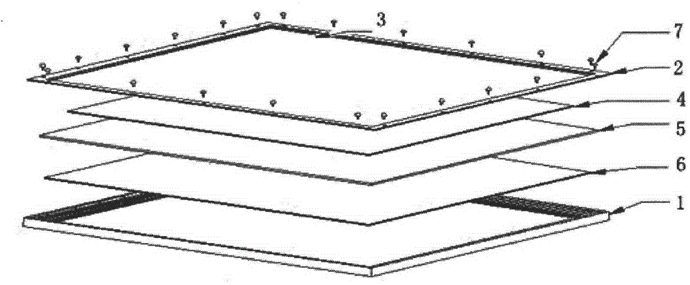
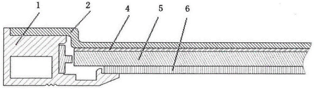
[0012] See figure 1 and figure 2 As shown, a LED panel lamp back panel mechanism has a profile frame 1 and a back panel 2 fixed on the profile frame 1 by screws 7. The back panel 2 is a square frame surface, and its upper surface is stamped into a square groove 3 , the convex surface of the groove 3 is in pressure contact with the surface of the reflective film 4 . A light guide plate 5 is arranged between the profile frames 1 and between the back plates 2 , and the upper surface of the light guide plate 5 is in contact with the reflective film 4 . A diffuser plate 6 is also provided between the profile frames 1 and between the back plates 2 , the upper surface of the diffuser plate 6 is connected to the light guide plate 5 , and the lower surface thereof is connected to the profile frame 1 .

[0013] The specific embodiments described above have further described the purpose, technical solutions and beneficial effects of the present invention in detail. It should be unders...


PUM


Abstract

The invention provides an LED panel light back plate mechanism. The LED panel light back plate mechanism comprises a profile frame and a back plate pressed on the profile frame. The back plate is a square frame face. A square groove is formed in the upper surface of the back plate through punching. The protruding face of the groove is connected with the surface of a reflection film in a pressing manner. According to the LED panel light back plate mechanism, the LED panel light back plate is punched into the shape with the groove in the middle from the plane shape, and the bottom of the face of the groove of the back plate is directly pressed on the upper face of reflection paper. By means of the LED panel light back plate mechanism, EVA flame-retardant foam used in the traditional process is saved, and the lamp cost is saved. The back plate made of metal is directly attached to the reflection film, the LED panel light back plate mechanism is smoother, and the production reject ratio is decreased.

Description

technical field [0001] The invention relates to the field of LED lighting, in particular to an LED panel light backboard mechanism. Background technique [0002] At present, in the LED panel lights with side-emitting on the market, almost all foam materials such as EVA are used between the back cover and the internal reflective film. The main function of this material is to attach the reflective film to the light guide plate evenly. The above technical methods have the following disadvantages: 1. The foam is large in size, and it is easy to be contaminated with dust, hair and other fine debris during production and transportation. The flat panel lamp generates a large amount of static electricity during the assembly process, and the above fine dust is adsorbed on Optical components, thereby reducing the qualified rate of flat panel light assembly, when the dust is not handled well, even the lamps have to be scrapped and replaced, resulting in greater material loss. 2. Foam ...

Claims


Application Information

Patent Timeline
IPC IPC(8): F21S2/00F21V15/02F21V13/12F21Y101/02
Inventor 乐成文
Owner CHANGZHOU ADVANCED OPTRONIC DEVICES
Why Eureka
Try Eureka