

Multi-connected air conditioner hot-water unit
A technology of multi-connected air conditioners and hot water units, which is applied in air conditioning systems, space heating and ventilation, heating methods, etc., and can solve problems such as inability to realize indoor unit communication
- Summary
- Abstract
- Description
- Claims
- Application Information
AI Technical Summary
Problems solved by technology
Method used
Image

Examples
Embodiment 1
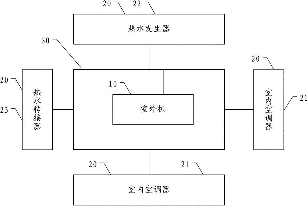
[0031] figure 1 It is a structural diagram of a multi-connected air conditioner and hot water unit provided in the embodiment of this application.
[0032] Such as figure 1 As shown, the multi-connected air conditioner and hot water unit provided in this embodiment includes an outdoor unit 10 , multiple indoor units 20 and a communication bus 30 .
[0033] Wherein the outdoor unit 10 is an outdoor unit located outdoors, and the multiple indoor units 20 include at least one indoor air conditioner 21 , a hot water generator 22 and a hot water adapter 23 .
[0034] The outdoor unit 10 is connected to the communication bus 30, and can output data to the communication bus 30 or receive data from the communication bus 30, and a plurality of indoor units are also respectively connected to the communication bus 30, and can also output data to the bus 30 Or receive data from the communication bus 30 .
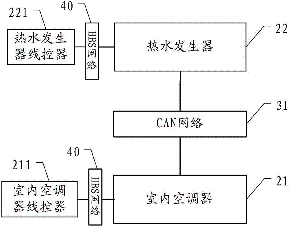
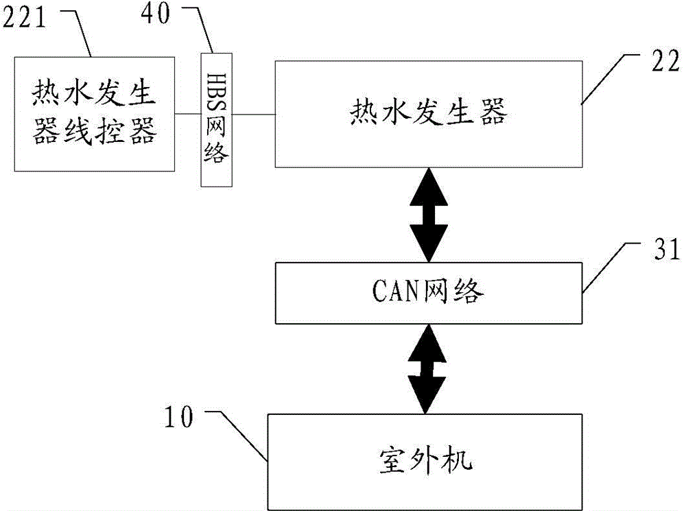
[0035] The communication bus 30 in this embodiment is preferably a CAN (Controll...
Embodiment 2
[0044] Figure 4 It is a structural diagram of a multi-connected air conditioner and hot water unit provided in another embodiment of the present application.
[0045] Such as Figure 4 As shown, the multi-connected air-conditioning and hot water unit provided in this embodiment is based on the previous embodiment with an additional floor heating valve and a floor heating heater (not shown). The floor heating valve is used to connect the hot water generator 22 with the floor heating Coil (not shown). The floor heating valve 24 is connected with the CAN bus 31 .
[0046]Set the network address correspondence between the indoor air conditioner A and the floor heating valve A through the water heater wire controller (not shown), where both are installed in room A, and set the network address correspondence between the indoor air conditioner B and the floor heating valve B, where both are installed In room B, by receiving the information of indoor air conditioner A and indoor a...
Embodiment 3
[0051] Figure 5 A structural diagram of a multi-connected air-conditioning water heater group provided for another embodiment of the present application.
[0052] Such as Figure 5 As shown, the multi-connected air-conditioning and hot water unit provided in this embodiment is based on the previous embodiment with the addition of a solar water heating device 50 .
[0053] The solar water heating device 50 communicates with the hot water generator 22, and is connected with the CAN bus 31 signal, for utilizing solar energy to obtain hot water and correspondingly replenishing the hot water generator 22, while being connected through the CAN bus 22 can Ensure that it works under unified control and coordination.
[0054] In order to ensure the normal operation of the solar water heating device 50, an electric heater (not shown) can be added in the solar water heating device 50 to protect the safety when working in a low temperature area and avoid being damaged by freezing and c...
PUM
 Abstract
Description
Claims
Application Information