An eps-based power supply control and diagnosis protection system and control method
A protection system and power control technology, applied in the direction of emergency protection circuit devices, electrical components, circuit devices, etc., can solve the problems of failure to meet the requirements of safety protection functions, single design of diagnostic methods, and few power supply output voltage circuits, etc., to achieve safety performance Guarantee, good reliability, effect of ensuring safety and reliability
- Summary
- Abstract
- Description
- Claims
- Application Information
AI Technical Summary
Problems solved by technology
Method used
Image
Examples
Embodiment 1
[0042] This embodiment provides an EPS-based power supply control and diagnosis protection system, including a power supply module, an ignition circuit, and an MCU module. In this embodiment, the MCU module is an MCU chip, which is used for programming control and diagnosis processing of various signals of the power supply, but is not limited to this function.
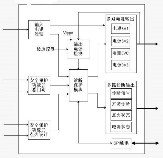
[0043] Such as figure 1 As shown, the power module includes an input power processing module for boosting and stabilizing an external battery power supply, an output power detection module, a diagnostic protection module, and a multi-channel power output module and a multi-channel diagnostic output module connected to the diagnostic protection module. , SPI communication module, and watchdog power module; the input power processing module is connected to the multi-channel power output module and the diagnosis protection module to provide power for them; the output power detection module performs overvoltage / undervoltag...
Embodiment 2
[0063] The difference between this embodiment and Embodiment 1 is that it also includes a soft-start power supply circuit connected to the MCU chip.
[0064] Such as Figure 5As shown, the soft start control is generated by the MCU chip according to the ignition signal, and is connected to the base of the band-stop transistor V704; the emitter of the transistor V704 is connected to the ground, and the collector is connected to the resistor R711; the resistor R711 is connected to the transistor The base of V703 is connected; the collector of the triode V703 is connected to +12V, and the emitter is connected to the resistor R712 at the same time; The contacts 3 and 4 are connected to form the load output of the soft start circuit.
[0065] The design of the soft-start power supply circuit in this embodiment is simplified, and the voltage of the relay is gradually increased from zero to the rated voltage, so that the starting current of the relay during the action process is cha...
Embodiment 3
[0068] Such as Figure 12 As shown, the difference between this embodiment and Embodiment 2 is that it also includes a relay signal control circuit with safety protection.
[0069] Relay signal control circuit such as Figure 6 , the relay signal control is the PWM signal sent by the MCU chip, which is connected to the capacitor C050; the capacitor C050 is connected in series with the resistor R050 to 5V, and is connected to the base of the triode V050; the emitter of the triode V050 is connected to 5V; the triode The collector of V050 is grounded in series with capacitor C051, and connected to resistor R051 at the same time; the resistor R051 is connected in series with capacitor C052, grounded, and connected to the base of triode V051 at the same time; the emitter of triode V051 is grounded, and the collector is connected in series with resistor R052 The base of the triode V052 is connected afterwards; the emitter of the triode V052 is connected with the filtered power supp...
PUM
 Abstract
Description
Claims
Application Information
 - R&D
- Intellectual Property
- Life Sciences
- Materials
- Tech Scout
- Unparalleled Data Quality
- Higher Quality Content
- 60% Fewer Hallucinations
Browse by: Latest US Patents, China's latest patents, Technical Efficacy Thesaurus, Application Domain, Technology Topic, Popular Technical Reports.
© 2025 PatSnap. All rights reserved.Legal|Privacy policy|Modern Slavery Act Transparency Statement|Sitemap|About US| Contact US: help@patsnap.com


