Fingerprint image capturing device and fingerprint image capturing module thereof

A fingerprint imaging and capture module technology, applied in character and pattern recognition, optics, instruments, etc., can solve problems such as large size and inability to meet thin requirements

Inactive Publication Date: 2016-01-27
PACING TECH
View PDF5 Cites 1 Cited by
  • Summary
  • Abstract
  • Description
  • Claims
  • Application Information

AI Technical Summary

Problems solved by technology

[0003] The embodiment of the present invention is to provide a fingerprint image capture device and its fingerprint image capture module, which can at least solve the defect that "the existing optical fingerprint recognition devices generally have a large size and cannot meet the thinning requirements".

Method used


Image

  • Fingerprint image capturing device and fingerprint image capturing module thereof
  • Fingerprint image capturing device and fingerprint image capturing module thereof
  • Fingerprint image capturing device and fingerprint image capturing module thereof

Examples


no. 1 example 〕

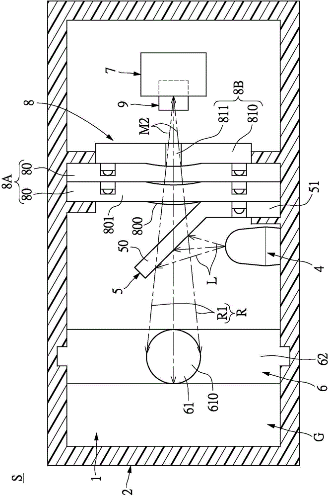
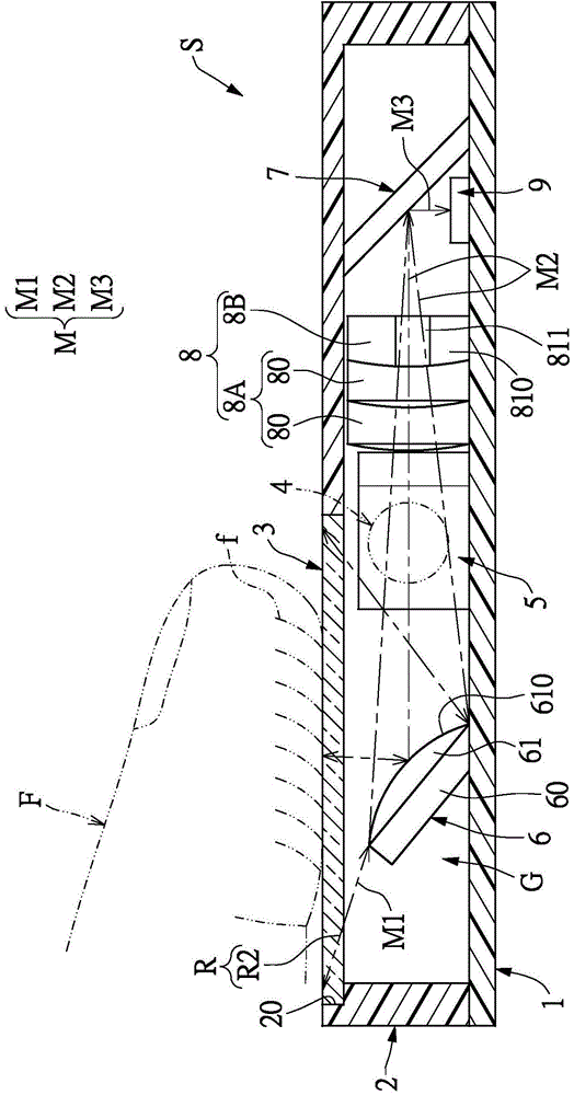
[0048] see Figure 1 to Figure 3 shown, where figure 2 for figure 1 A schematic cross-sectional view of the A-A cut surface line, image 3 for figure 1 Schematic cross-sectional view of the B-B section line. As can be seen from the above figures, the first embodiment of the present invention provides a fingerprint image capture device S, which includes: a circuit substrate 1, an outer shell 2, a light-transmitting element 3 and a fingerprint image capture module G, wherein The fingerprint image capture module G is arranged in the outer casing 2, and the fingerprint image capture module G includes a light emitting element 4, a light splitting element 5, a first reflective element 6, a second reflective element 7, a lens assembly 8 and A fingerprint image sensing element 9 .

[0049] First, cooperate figure 1 and image 3As shown, the outer casing 2 is arranged on the circuit substrate 1 , wherein the top of the outer casing 2 has a top opening 20 , and the light-transmi...

no. 2 example

[0057] see Figure 4 to Figure 5 As shown, the second embodiment of the present invention provides a fingerprint image capture module G, which includes a light emitting element 4, a light splitting element 5, a first reflective element 6, a second reflective element 7, a lens assembly 8 and A fingerprint image sensing element 9 . Wherein, the light splitting element 5 is arranged in front of the light emitting element 4 . The first reflective element 6 is disposed on one side of the light-splitting element 5 at a first predetermined distance from the light-splitting element 5 , wherein the first light-reflecting element 6 has a light-reflecting curved surface 610 . The second reflective element 7 is disposed on the other side of the light splitting element 5 and is separated from the light splitting element 5 by a second predetermined distance. The lens assembly 8 is disposed between the light splitting element 5 and the second reflective element 7 . The fingerprint image s...


PUM


Abstract

A fingerprint image capturing module includes a light-emitting element, a light-splitting element, a first light-reflecting element, a second light-reflecting element, a lens assembly and a fingerprint image sensing element, characterized in that: a projection light beam generated by the light-emitting element is reflected by the light-splitting element and the first light-reflecting element in sequence to form an illumination light beam that passes through a light-transmitting element and is projected onto a fingerprint of a finger, the illumination light beam is reflected by the finger to form an image light beam that is reflected by the first light-reflecting element, the image light beam sequentially passes through the light-splitting element and the lens assembly and is projected onto the fingerprint image sensing element through the second light-reflecting element, and the fingerprint image sensing element receives the image light beam to obtain a fingerprint image of the fingerprint of the finger.

Description

technical field [0001] The invention relates to a fingerprint image capture device and its fingerprint image capture module, in particular to a fingerprint image capture device and its fingerprint image capture module which can meet the requirement of thinning. Background technique [0002] Generally speaking, the usual way for a fingerprint identification device to read a fingerprint is to read the fingerprint with a fixed finger. For example, a pressing plate can be used for finger contact, and multiple light-emitting elements can be used to provide the light source required for “when the lens is to capture the fingerprint image of the finger that has touched the pressing plate”. In order to meet the principle of total reflection, this kind of fingerprint identification device must have a specific angle between the lens, finger and light source, so as to capture obvious and clear fingerprint images, so the existing optical fingerprint identification device There are commo...

Claims


Application Information

Patent Timeline
Patent Type & Authority Applications(China)
IPC IPC(8): G06K9/20G02B27/10G02B17/08
CPCG06V40/1312G06V40/1324
Inventor 曾吉旺
Owner PACING TECH
Why Eureka
Try Eureka