Demonstration model of difference of internal pressure and external pressure of spherical liquid level

A technology of pressure difference and liquid level, applied in teaching models, educational tools, instruments, etc.

Inactive Publication Date: 2016-01-27
韩秋红
View PDF3 Cites 1 Cited by
  • Summary
  • Abstract
  • Description
  • Claims
  • Application Information

AI Technical Summary

Problems solved by technology

[0006] In order to solve the problems of the prior art, the present invention designs a ...

Method used


Image

  • Demonstration model of difference of internal pressure and external pressure of spherical liquid level
  • Demonstration model of difference of internal pressure and external pressure of spherical liquid level
  • Demonstration model of difference of internal pressure and external pressure of spherical liquid level

Examples


Embodiment 1

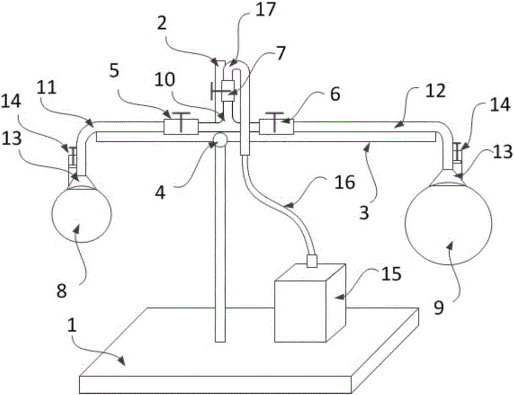
[0020] Such as figure 2 Shown: a demonstration model of the pressure difference between the inside and outside of a spherical liquid surface, including a base 1 with a bracket on the base, the bracket includes a support bar 2 and a cross bar 3, and the cross bar 3 can move up and down and left and right on the support bar through the fixing frame 4 . A T-shaped glass three-way conduit 10 is fixed on the crossbar 3, and the two ports of the T-shaped glass three-way conduit 10 are connected with 90° glass elbows 11 and 12 through switch valves 5 and 6 respectively. The vertical port of the three-way conduit 10 is connected with the air blowing pipe 17 through the switching valve 7, and the end of the 90° glass elbow is connected with the bell mouth 13. On-off valves 5, 6 and 7 are water stop clamps in this embodiment of the invention. The use of water-stop clamps can make the conduction process of the pipeline relatively smooth, and avoid rapid fluctuations in the size of the...


PUM


Abstract

The invention relates to a demonstration model of a difference of an internal pressure and an external pressure of a spherical liquid level. The demonstration model comprises a pedestal and a soapy water providing unit. A support is arranged on the pedestal and contains a support rod and a cross rod; a T-shaped glass three-way guiding tube is fixed on the cross rod; two horizontal straight openings of the T-shaped glass three-way guiding tube are connected with 90-degree bending glass tubes by switching valves; a vertical opening of the T-shaped glass three-way guiding tube is connected with an air blowpipe by a switching valve; and horn mouths are connected to the tail ends of the bending glass tubes. Soap bubbles with different sizes are blown by the two horn mouths; and because the air pressure in the small soap bubble is larger than that in the large soap bubble, the small soap bubble is reduced continuously and the large soap bubble is increased continuously. Therefore, the conclusion of the difference of the internal pressure and the external pressure of the spherical liquid level can be tested simply and ingeniously.

Description

technical field [0001] The invention relates to the field of experimental devices, in particular to a demonstration model of pressure difference inside and outside a spherical liquid surface. Background technique [0002] Such as figure 1 Shown: the additional pressure under the spherical liquid surface with a radius of R, a spherical cap-shaped small liquid block is isolated at the liquid surface, and its force condition is analyzed, it can be seen that this small liquid block is affected by three parts : The first part: is the surface tension acting on the liquid block through the edge of the small liquid block; the second part: is caused by the additional pressure p, and passes through the bottom surface (the area is πr 2 ) force pπr acting on the liquid block 2 , in fact the lower part of the liquid passes through the bottom surface πr 2 There is pressure acting on the liquid block, and the external medium (such as the atmosphere) also has pressure acting on the liqui...

Claims


Application Information

Patent Timeline
IPC IPC(8): G09B23/12
CPCG09B23/12
Inventor 呼格吉乐韩秋红张天声
Owner 韩秋红
Why Eureka
Try Eureka