CNFET (Carbon Nanotube Field Effect Transistor)-based single-edge pulse signal generator

A technology of pulse signal and generator, which is applied in the direction of pulse generation, pulse technology, electric pulse generation, etc. It can solve the problems of low speed, increased short-circuit power consumption, and increased power consumption of single-edge pulse signal generators.

Active Publication Date: 2016-01-27
NINGBO UNIV
View PDF5 Cites 6 Cited by
  • Summary
  • Abstract
  • Description
  • Claims
  • Application Information

AI Technical Summary

Problems solved by technology

Analysis of the single-edge pulse signal generator shows that the gate-grounded PMOS transistor M1 is always on, and a short-circuit path from the power supply VDD to the ground will be formed when the discharge path is turned on, which increases the sh

Method used


Image

  • CNFET (Carbon Nanotube Field Effect Transistor)-based single-edge pulse signal generator
  • CNFET (Carbon Nanotube Field Effect Transistor)-based single-edge pulse signal generator
  • CNFET (Carbon Nanotube Field Effect Transistor)-based single-edge pulse signal generator

Examples


Embodiment 1

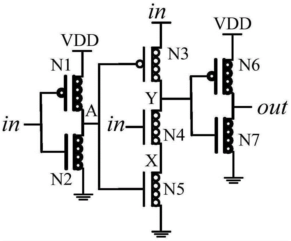
[0016] Embodiment one: if figure 2 As shown, a CNFET-based single-edge pulse signal generator includes a first CNFET tube N1, a second CNFET tube N2, a third CNFET tube N3, a fourth CNFET tube N4, a fifth CNFET tube N5, and a sixth CNFET tube N6 and the seventh CNFET tube N7, the first CNFET tube N1, the third CNFET tube N3 and the sixth CNFET tube N6 are P-type CNFET tubes, the second CNFET tube N2, the fourth CNFET tube N4, the fifth CNFET tube N5 and the sixth CNFET tube The seven CNFET tubes N7 are N-type CNFET tubes; the source of the first CNFET tube N1, the substrate of the first CNFET tube N1, the substrate of the third CNFET tube N3, the source of the sixth CNFET tube N6 and the sixth CNFET tube The substrates of N6 are all connected to the power supply VDD, the gate of the first CNFET N1, the gate of the second CNFET N2, the source of the third CNFET N3 and the gate of the fourth CNFET N4 are connected and their connection terminals It is the signal input terminal ...

Embodiment 2

[0019] Embodiment two: if figure 2 As shown, a CNFET-based single-edge pulse signal generator includes a first CNFET tube N1, a second CNFET tube N2, a third CNFET tube N3, a fourth CNFET tube N4, a fifth CNFET tube N5, and a sixth CNFET tube N6 and the seventh CNFET tube N7, the first CNFET tube N1, the third CNFET tube N3 and the sixth CNFET tube N6 are P-type CNFET tubes, the second CNFET tube N2, the fourth CNFET tube N4, the fifth CNFET tube N5 and the sixth CNFET tube The seven CNFET tubes N7 are N-type CNFET tubes; the source of the first CNFET tube N1, the substrate of the first CNFET tube N1, the substrate of the third CNFET tube N3, the source of the sixth CNFET tube N6 and the sixth CNFET tube The substrates of N6 are all connected to the power supply VDD, the gate of the first CNFET N1, the gate of the second CNFET N2, the source of the third CNFET N3 and the gate of the fourth CNFET N4 are connected and their connection terminals It is the signal input terminal ...


PUM

PropertyMeasurementUnit
Diameteraaaaaaaaaa
Diameteraaaaaaaaaa

Abstract

The invention discloses a CNFET (Carbon Nanotube Field Effect Transistor)-based single-edge pulse signal generator. The CNFET-based single-edge pulse signal generator comprises a first CNFET, a second CNFET, a third CNFET, a fourth CNFET, a fifth CNFET, a sixth CNFET and a seventh CNFET, wherein the first CNFET, the third CNFET and the sixth CNFET are P-type CNFETs; the second CNFET, the fourth CNFET, the fifth CNFET and the seventh CNFET are N-type CNFETs; a grid of the first CNFET, a grid of the second CNFET and a source of the third CNFET are connected with a grid of the fourth CNFET; a drain of the first CNFET, a drain of the second CNFET and a grid of the third CNFET are connected with a grid of the fifth CNFET; a drain of the third CNFET, a drain of the fourth CNFET and a grid of the sixth CNFET are connected with a grid of the seventh CNFET; a source of the fourth CNFET is connected with a drain of the fifth CNFET; and a drain of the sixth CNFET is connected with a drain of the seventh CNFET. The CNFET-based single-edge pulse signal generator has the remarkable characteristics of high speed and low power consumption.

Description

technical field [0001] The invention relates to a pulse signal generator, in particular to a CNFET-based single-edge pulse signal generator. Background technique [0002] As the basis of sequential circuits, flip-flops usually account for 20%-50% of circuit power consumption. High-performance flip-flops are conducive to speeding up the speed of integrated circuits and reducing circuit power consumption. Compared with the master-slave flip-flop, the pulse flip-flop can effectively reduce the delay between circuits, and the single-latch structure also greatly simplifies the circuit design. A dominant pulse flip-flop is composed of an independent pulse signal generator and a latch. As a separate part, the pulse signal generator can share the pulse signal with multiple dominant pulse flip-flops, thus effectively saving hardware overhead and reducing large-scale circuit power consumption. The design of the pulse signal generator in the dominant pulse trigger will affect the com...

Claims


Application Information

Patent Timeline
IPC IPC(8): H03K3/012
Inventor 王谦汪鹏君龚道辉
Owner NINGBO UNIV
Why Eureka
Try Eureka