Cable connection structure
A cable and structure technology, applied in the field of cable connection structure, to achieve the effect of reducing the installation height
- Summary
- Abstract
- Description
- Claims
- Application Information
AI Technical Summary
Problems solved by technology
Method used
Image

Examples
Embodiment approach 1
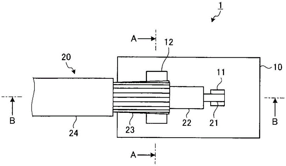
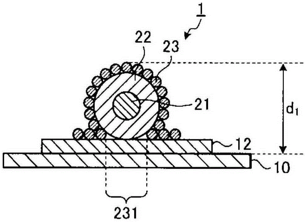
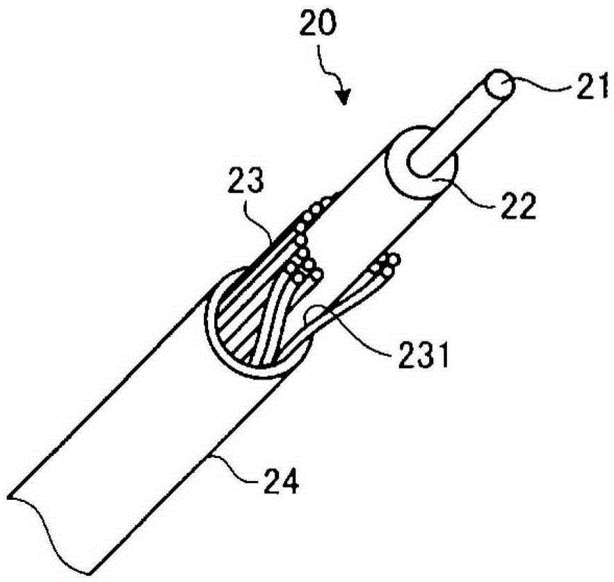
[0041] figure 1 It is a schematic diagram which shows the schematic structure of the cable connection structure of Embodiment 1 of this invention. figure 2 Yes figure 1 A-A line cross-sectional view of the cable connection structure shown. image 3 It is a perspective view schematically showing a cable of the cable connection structure of the first embodiment. Figure 4 Yes figure 1 A cross-sectional view along the line B-B of the cable connection structure shown. The cable connection structure 1 of the first embodiment includes a board 10 on which electronic components and the like are mounted, and a cable 20 connected to the board 10. Hereinafter, the description will be made assuming that the cable 20 is a coaxial cable.
[0042] The substrate 10 has a substantially flat plate shape, and a circuit, electrodes, etc. are formed on at least one main surface. In addition, a first electrode 11 and a second electrode 12 that are electrically connected to the cable 20 are formed on ...
Embodiment approach 2
[0054] Figure 5 It is a schematic diagram which shows the schematic structure of the cable connection structure of Embodiment 2 of this invention. Image 6 Yes Figure 5 The C-C line cross-sectional view of the cable connection structure shown. In addition, the same components as those described above are given the same reference numerals for description. The cable connection structure 1a of the second embodiment connects a plurality of the above-mentioned cables 20 to the substrate 10a.
[0055] The substrate 10a has a substantially flat plate shape, and a circuit, electrodes, etc. are formed on at least one main surface. A plurality of first electrodes 11 electrically connected to the cables 20 are formed on one main surface of the substrate 10a. In addition, a second electrode 12 a extending in the arrangement direction of the plurality of cables 20 and connected to the shield 23 of the plurality of cables 20 is formed on one main surface of the substrate 10 a. The second e...
Embodiment approach 3
[0061] Figure 7 It is a schematic diagram which shows the schematic structure of the cable connection structure of Embodiment 3 of this invention. Figure 8 Yes Figure 7 D-D line cross-sectional view of the cable connection structure shown. In addition, the same components as those described above are given the same reference numerals for description. The cable connection structure 1b of this Embodiment 3 has the board|substrate 10b on which electronic components etc. are mounted, and the cable 20a connected to the board|substrate 10b.
[0062] The substrate 10b has a substantially flat plate shape, and a circuit, electrodes, etc. are formed on at least one main surface. A first electrode 11 electrically connected to the cable 20a and a second electrode 12b connected to the shield 23a of the cable 20a are formed on one main surface of the substrate 10b. The second electrode 12b is a ground electrode.
[0063] The cable 20a has: the above-mentioned core wire 21 and the internal ...
PUM
 Abstract
Description
Claims
Application Information
 - Generate Ideas
- Intellectual Property
- Life Sciences
- Materials
- Tech Scout
- Unparalleled Data Quality
- Higher Quality Content
- 60% Fewer Hallucinations
Browse by: Latest US Patents, China's latest patents, Technical Efficacy Thesaurus, Application Domain, Technology Topic, Popular Technical Reports.
© 2025 PatSnap. All rights reserved.Legal|Privacy policy|Modern Slavery Act Transparency Statement|Sitemap|About US| Contact US: help@patsnap.com