Balance weight device of boring-milling machine

A technology of a counterweight device and a boring and milling machine, which is used in maintenance and safety accessories, metal processing machinery parts, metal processing equipment, etc., can solve the problems of falling counterweight blocks, swinging counterweight blocks from side to side, and easy breakage of connecting ropes. achieve the effect of avoiding falling

Active Publication Date: 2016-02-03
TONGYU HEAVY IND
View PDF6 Cites 7 Cited by
  • Summary
  • Abstract
  • Description
  • Claims
  • Application Information

AI Technical Summary

Problems solved by technology

The motor drives the boring box to move up and down, and the counterweight moves up and down along the steel pipe on the inner wall of the column. When moving up and down, the counterweight will shake left and right. The counterweight is connected with the connecting rope. Under the action, the connecting rope is easy to break, causing the counterweight to fall from a high place, and smashing the bed and motor and other components under the column

Method used


Image

  • Balance weight device of boring-milling machine
  • Balance weight device of boring-milling machine
  • Balance weight device of boring-milling machine

Examples


Embodiment Construction

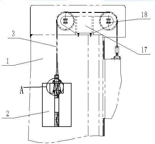
[0022] A counterweight device for a boring and milling machine includes a hollow column 1, a counterweight 2 arranged in the column, a support device positioned above the column 1, and a connecting rope 3 connecting the counterweight 2 and the driving device through the support device, which It is characterized in that a vertical guide rail 4 is provided opposite to each other on the inner wall of the column 1, grooves 5 corresponding to the guide rails 4 are provided on both sides of the counterweight 2, and grooves 5 are provided on the grooves 5. A buckle device that can fix the counterweight 2 on the guide rail 4, and the counterweight 2 is provided with a control structure for controlling the buckle device.

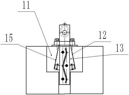
[0023] Specifically, the control structure includes a load-bearing block 6 located at the upper end of the counterweight 2, the two sides of the load-bearing block 6 are protruding flanges 7, and each of the flanges 7 is provided with a snap-on The briquetting block ...


PUM


Abstract

A balance weight device of a boring-milling machine comprises a hollow stand column, a balance weight block arranged in the stand column, a supporting device located above the stand column, and a connecting rope connected with the balance weight block and a drive device through the supporting device. The balance weight device is characterized in that vertical guide rails are oppositely arranged on the inner walls of the stand column respectively, grooves corresponding to the guide rails are formed in the two sides of the balance weight block, the grooves are provided with buckle devices capable of fixing the balance weight block to the guide rails, and the balance weight block is provided with a control structure used for controlling the buckle devices.

Description

technical field [0001] The invention relates to a counterweight device, in particular to a counterweight device for a boring and milling machine. Background technique [0002] In the current field of CNC boring and milling machines, especially the counterweight of CNC boring and milling machines, the pulley seat is set on the top of the column, the pulleys are arranged along the axial horizontal direction, the weight of the counterweight and the boring box are matched, and the counterweight and the boring box are respectively located Both sides of the pulley are lower than the height of the pulley, and the connecting rope passes through the pulley and is fixedly connected to the counterweight and the boring box respectively. The motor drives the boring box to move up and down, and the counterweight moves up and down along the steel pipe on the inner wall of the column. When moving up and down, the counterweight will shake left and right. The counterweight is connected with t...

Claims


Application Information

Patent Timeline
Patent Type & Authority Applications(China)
IPC IPC(8): B23Q11/00
CPCB23Q11/0025
Inventor 司兴奎刘殿山刘宝钢李立强张帅范佳佳
Owner TONGYU HEAVY IND
Why Eureka
Try Eureka