A wire drawing device for door panel surface

A door panel surface and door panel technology, which is applied to the parts of grinding machine tools, grinding workpiece supports, grinding machines, etc., can solve the problem of wire drawing direction, uneven depth, dust damage to workers' physical and mental health, and different effects of drawing lines, etc. problem, to achieve the effect of novel and unique structural composition, high degree of automation, stable direction and strength

Active Publication Date: 2018-02-06
GUANGXI SHUANGYING DOORS CO LTD
View PDF4 Cites 0 Cited by
  • Summary
  • Abstract
  • Description
  • Claims
  • Application Information

AI Technical Summary

Problems solved by technology

[0003] The traditional wire drawing process is to use a scouring pad to draw wire on the door panel. This public wire drawing method has very low work efficiency
Moreover, when workers are operating, the smell of paint is choking, and the dust generated will also harm the physical and mental health of workers.
In addition, during the working period, due to the unstable strength and direction of the workers, the direction and depth of the drawn wires are not uniform enough, and the effect of the drawn lines is also different, which in turn affects the appearance of the door.

Method used


Image

  • A wire drawing device for door panel surface
  • A wire drawing device for door panel surface
  • A wire drawing device for door panel surface

Examples


Embodiment Construction

[0038] Now in conjunction with accompanying drawing, the present invention is described in detail:

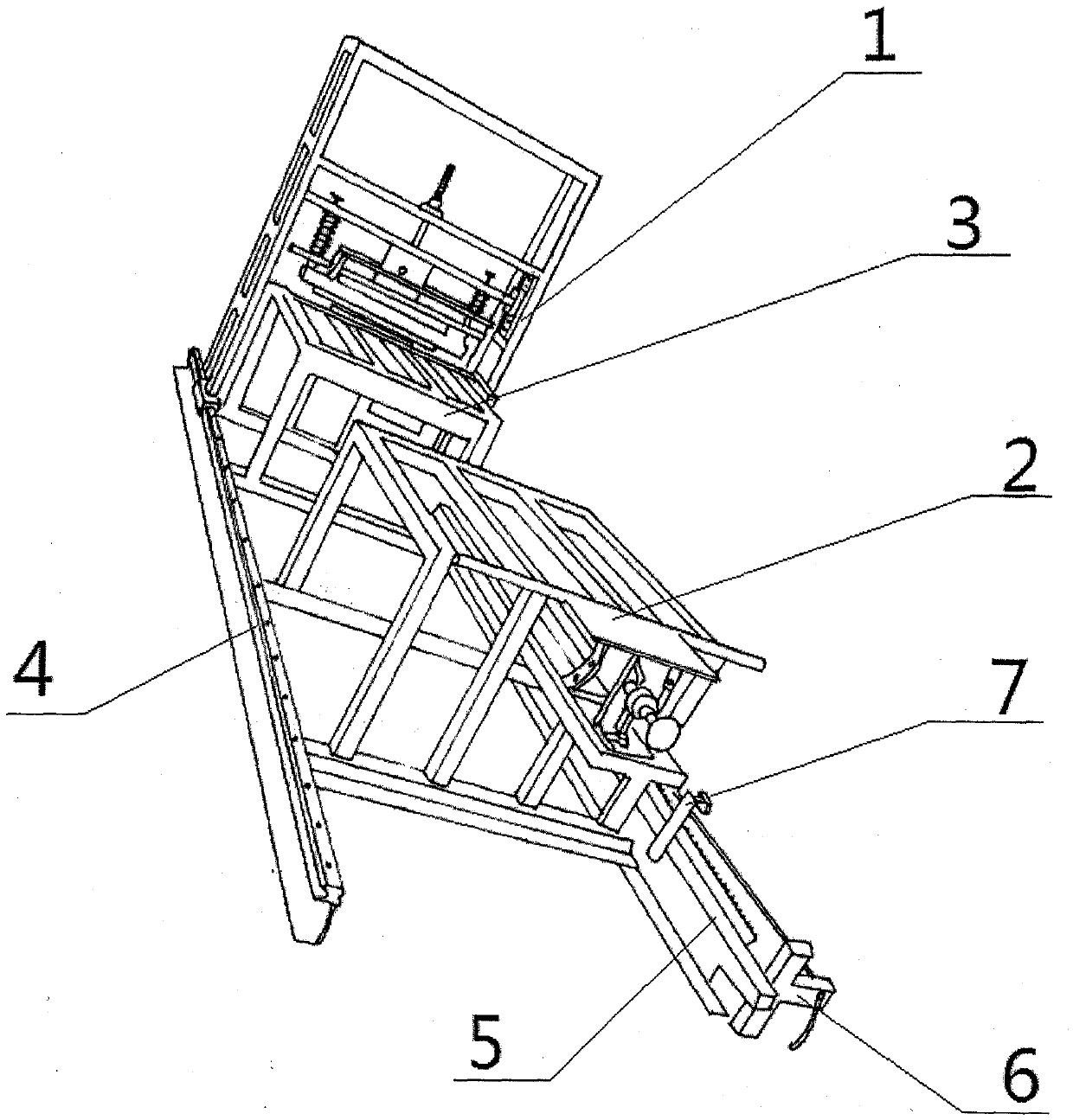
[0039]The present invention is composed of a wire drawing machine transmission frame (1), a front frame (2) for placing a door panel, a rear frame (3) for placing a door panel, a guide rail (4), a gear guide rail (5), a solenoid valve (6), and a wire fixing frame (7). )composition.

[0040] figure 1 Shown is the structural representation of the present invention. Among them, 1 is the wire drawing machine transmission frame (1), 2 is the front frame for door panel placement (2), 3 is the rear frame for door panel placement (3), 4 is the guide rail (4), 5 is the gear guide rail (5), and 6 is the electromagnetic Valve (6), 7 are electric wire holders (7).

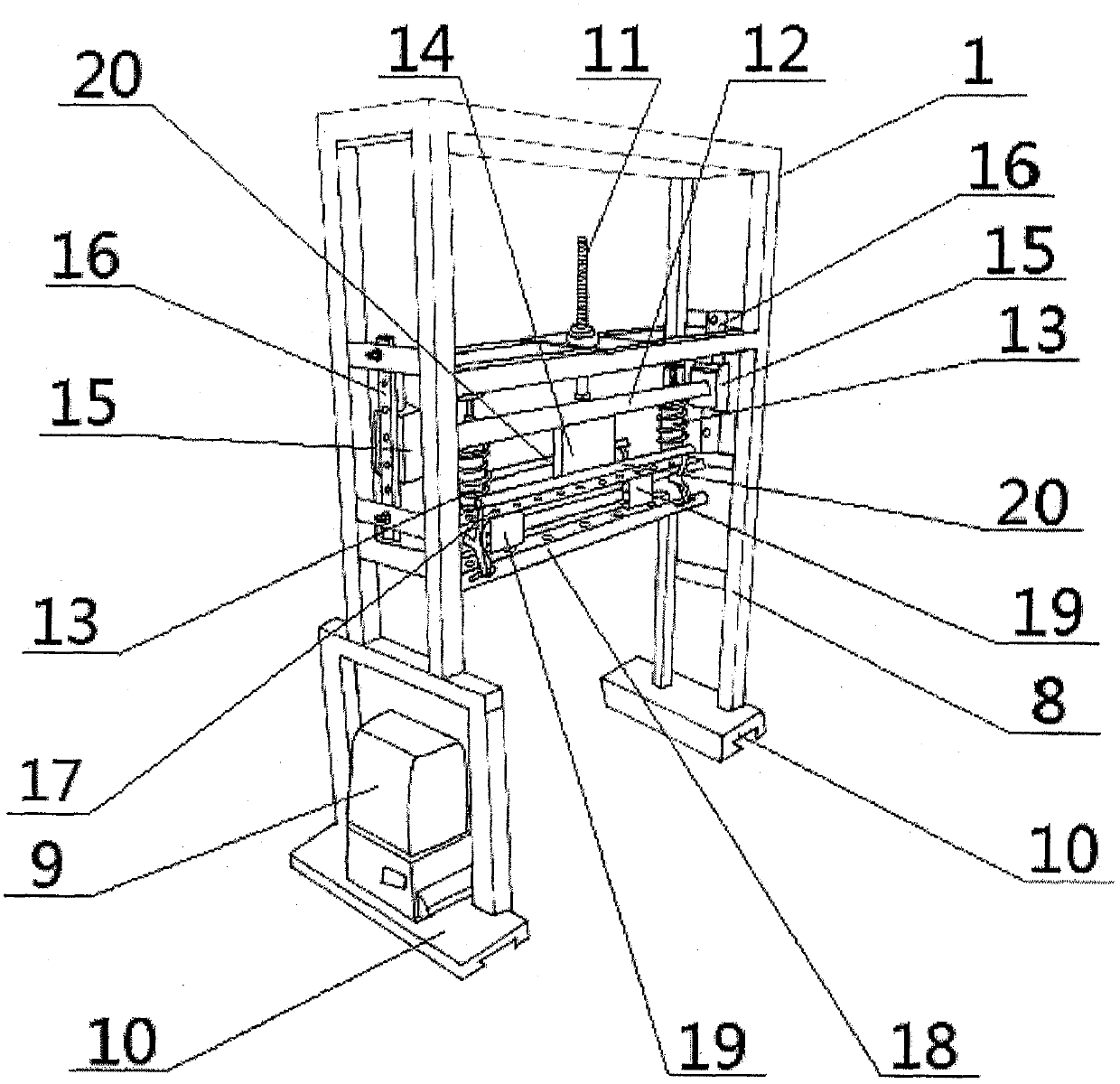
[0041] figure 2 Shown is the schematic structural view of the wire drawing machine driving frame (1) in the present invention. The wire drawing machine transmission frame (1) is composed of a frame body two (8), a motor (...


PUM


Abstract

A wiredrawing device for a door plank face is composed of a wiredrawing machine transmission frame, a front door plank mounting frame, a rear door plank mounting frame, guide rails, a gear guide rail, a solenoid valve and an electric wire fixing frame. The front door plank mounting frame is arranged in front of the wiredrawing machine transmission frame. The rear door plank mounting frame is arranged below the wiredrawing machine transmission frame. The two guide rails are arranged on the two sides of the front door plank mounting frame and the rear door plank mounting frame respectively. The gear guide rail is arranged on the left side of the front door plank mounting frame and the rear door plank mounting frame. The wiredrawing machine transmission frame is arranged on the two guide rails. A gear of a motor is arranged on the gear guide rail. The solenoid valve is arranged at the front end of the gear guide rail. The electric wire fixing frame is arranged beside the gear guide rail. In this way, the whole wiredrawing device is formed. By the adoption of the wiredrawing device, the wiredrawing direction and strength are stable, the wiredrawing direction and the depth of wiredrawing are even, and the effect is stable as well. Meanwhile, the wiredrawing device is high in automation degree and working efficiency, and wiredrawing door planks with high quality can be manufactured with unskilled workers.

Description

technical field [0001] The invention belongs to a supporting facility for door panel production, in particular to a wire drawing device for door panel surfaces. Background technique [0002] In order to improve the attractive in appearance of door panel, door panel all is to realize by spraying paint coloring generally. At present, some enterprises also draw some lines on the door panel to make the appearance of the door panel more delicate and beautiful, thereby improving the quality of the door panel and greatly increasing the value of the door panel. [0003] The traditional wire drawing process is to manually use a scouring pad to draw wire on the door panel. This public wire drawing method has very low work efficiency. Moreover, when workers are operating, the smell of paint is choking, and the dust generated will also harm the physical and mental health of workers. In addition, during the working period, due to the unstable strength and direction of the workers, the ...

Claims


Application Information

Patent Timeline
Patent Type & Authority Patents(China)
IPC IPC(8): B24B27/00B24B41/06B24B41/00
CPCB24B27/00B24B41/00B24B41/068
Inventor 覃安宁
Owner GUANGXI SHUANGYING DOORS CO LTD
Why Eureka
Try Eureka