Die-cutting machine for inner hole cutting and production equipment for pet protective film

A die-cutting machine and inner hole technology, applied in metal processing and other directions, can solve the problem of manual removal of waste

Active Publication Date: 2018-05-08
SHENZHEN XIMENGTE ELECTRONICS CO LTD
View PDF10 Cites 0 Cited by
  • Summary
  • Abstract
  • Description
  • Claims
  • Application Information

AI Technical Summary

Problems solved by technology

[0004] Aiming at the aforementioned problem that the waste in the glue-free area of ​​the inner hole of the PET protective film needs to be manually removed, the present invention provides a film cutting machine for cutting the inner hole and a production equipment for the PET protective film.

Method used


Image

  • Die-cutting machine for inner hole cutting and production equipment for pet protective film
  • Die-cutting machine for inner hole cutting and production equipment for pet protective film
  • Die-cutting machine for inner hole cutting and production equipment for pet protective film

Examples


Embodiment Construction

[0027] In order to make the technical problems, technical solutions and beneficial effects solved by the present invention clearer, the present invention will be further described in detail below in conjunction with the accompanying drawings and embodiments. It should be understood that the specific embodiments described here are only used to explain the present invention, not to limit the present invention.

[0028] In the description of the present invention, it should be noted that unless otherwise specified and limited, the term "connection" should be understood in a broad sense, for example, it can be a fixed connection, a detachable connection, or an integral connection; for Those of ordinary skill in the art can understand the specific meanings of the above terms in the present invention in specific situations.

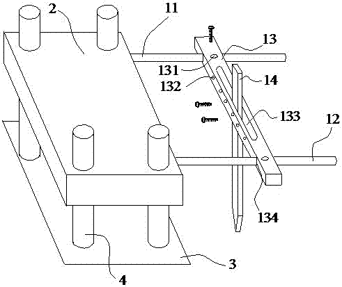
[0029] Such as figure 1 Shown is a schematic structural view of the first embodiment of the die-cutting machine for cutting inner holes of the present invent...


PUM


Abstract

The invention provides a die-cutting machine for cutting inner holes, which includes a die base, a cutting table, a blanking device and a vertical guide column; On the column, the side of the mold base facing the cutting table is equipped with an inner hole cutter; the blanking equipment includes the first guide column, the second guide column, the knife holder and the blanking cutter; the first guide column and the second guide column are both horizontal fixed on the mold base; the knife holder is assembled between the first guide post and the second guide post, and the blanking cutter is fixed on the knife holder. The invention also provides a production equipment for the PET protective film. The die-cutting machine provided by the invention can realize the automatic discharge of waste materials in inner holes and reduce the cost.

Description

technical field [0001] The invention relates to the field of moulds, in particular to a film cutting machine for cutting inner holes and production equipment for PET protective films. Background technique [0002] At present, PET-type protective films (see Figure 4 The production process of the quasi-elliptic annular ring b) is double-die cutting and sleeve cutting. First, the double-sided adhesive sent by the double-sided adhesive feeder and the release film sent by the release film feeder are processed by two round rollers. Press the roller to make the double-sided adhesive and the release film stick together to obtain the double-sided adhesive and the release film (the double-sided adhesive is covered on the release film); then, the double-sided adhesive and the release film The compound is sent to the first die-cutting machine to punch the inner hole of the double-sided adhesive tape; then, the double-sided adhesive release paper waste collection device is used to colle...

Claims


Application Information

Patent Timeline
Patent Type & Authority Patents(China)
IPC IPC(8): B26F1/38B26F1/16B26D7/18
Inventor 邹礼龙
Owner SHENZHEN XIMENGTE ELECTRONICS CO LTD
Why Eureka
Try Eureka