Door-motor system of shielding door

A screen door and door operator technology, which is applied to door/window accessories, power control mechanisms, wing leaf control mechanisms, etc., can solve the problems of the stability of the door system, the deformation of the door operator beam, and the large occupied space, etc., to achieve Reduce the difficulty of installation and maintenance, reduce the installation space, and improve the stability

Active Publication Date: 2016-02-03
PCI TECH & SERVICE CO LTD
View PDF6 Cites 2 Cited by
  • Summary
  • Abstract
  • Description
  • Claims
  • Application Information

AI Technical Summary

Problems solved by technology

[0003] At present, most of the gantry beams are large-sized L-shaped aluminum profiles. In this case, the guide rails are directly installed on the gantry beams. In this way, a movement gap needs to be reserved on both sides of the lintel channel steel and the guide rails, resulting in the occupied space during installation. The space is large, and the maintenance space in the door operator beam structure is relatively limited, which makes the installation and maintenance more complicated, and the external force is easy to act on the door operator beam through the guide rail, which is easy to cause the door operator beam to deform, which will have a great impact on the stability of the door system. influences

Method used


Image

  • Door-motor system of shielding door
  • Door-motor system of shielding door
  • Door-motor system of shielding door

Examples


Embodiment Construction

[0029] Below, in conjunction with accompanying drawing and specific embodiment, the present invention is described further:

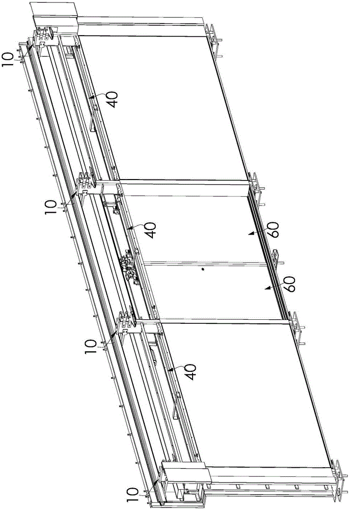
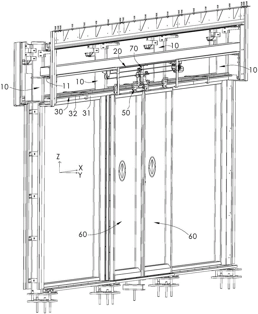
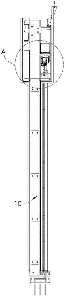
[0030] Such as Figure 1 to Figure 8 As shown, the screen door operator system of the present invention includes a column 10 , an in-line operator beam 20 , a guide rail 30 , a lintel channel steel 40 and a suspension assembly 50 . A plurality of upright columns 10 are distributed at intervals along the X-axis direction, and the same side of the plurality of upright columns 10 is provided with a protruding plate 11; the in-line door machine beam 20 extends along the X-axis direction, and the in-line door machine beam 20 is located on the One side of the plurality of columns 10 provided with the extension plates 11 is fixed on the plurality of extension plates 11; the guide rail 30 extends along the X-axis direction, and the guide rail 30 is fixed on the plurality of columns 10 provided with extensions. On one side of the panel 11, the guide rail 30 is ...


PUM


Abstract

A door-motor system of a shielding door comprises stand columns, a linear door-motor beam, a guide rail, door header box iron and hanging assemblies. Extending-out plates are arranged on the same sides of the stand columns. The linear door-motor beam extends in the X-axis direction and is located on the sides, provided with the extending-out plates, of the stand columns and fixedly arranged on the extending-out plates. The guide rail is fixedly arranged on the sides, provided with the extending-out plates, of the stand columns. The guide rail is located below the linear door-motor beam, and interval space is formed between the guide rail and the linear door-motor beam. The door header box iron is located on the side, far away from the stand columns, of the guide rail, extends in the X-axis direction and is located between the two adjacent stand columns. The hanging assemblies comprise installing frames and hanging wheels connected to the installing frames in a pivoted manner. The installing frames are used for being fixedly arranged at the upper end of the shielding door. The hanging wheels are hung on the guide rail and can move in the extending direction of the guide rail. According to the door-motor system of the shielding door, the installing space can be reduced, the installing and maintaining difficulty is lowered, and the stability of the door system is improved.

Description

technical field [0001] The invention relates to a screen door machine system. Background technique [0002] As a safe, environmentally friendly and energy-saving facility, subway screen doors have been widely used in urban rail transit. With the maturity of technology, there are higher requirements for the installation space and maintenance convenience of screen doors. [0003] At present, most of the door machine beams are large-sized L-shaped aluminum profiles. In this case, the guide rails are directly installed on the door machine beams. In this way, it is necessary to reserve a movement gap on both sides of the lintel channel steel and the guide rails, resulting in the occupied space during installation. The space is large, and the maintenance space in the door operator beam structure is relatively limited, which makes the installation and maintenance more complicated, and the external force is easy to act on the door operator beam through the guide rail, which is easy...

Claims


Application Information

Patent Timeline
IPC IPC(8): E05F15/643E05D13/00E05C19/00
Inventor 陈文才江景
Owner PCI TECH & SERVICE CO LTD
Why Eureka
Try Eureka