Drill rod connector

A technology for drill pipe joints and drill pipes, which is applied in the direction of drill pipes, drill pipes, and drilling equipment. Uniform seam and reliable sealing effect

Active Publication Date: 2016-02-03
CHTC JOVE HEAVY IND
View PDF6 Cites 6 Cited by
  • Summary
  • Abstract
  • Description
  • Claims
  • Application Information

AI Technical Summary

Problems solved by technology

[0003] The threaded connection method has the following disadvantages: a) The drill pipe with the threaded connection method can only implement forward rotation drilling operations, and the drill pipe must not be reversely rotated during construction operations, otherwise the drill pipe or drill bit will fall into the accident in the hole
c) Drill pipes with threaded

Method used


Image

  • Drill rod connector
  • Drill rod connector
  • Drill rod connector

Examples


Example Embodiment

[0034] Example

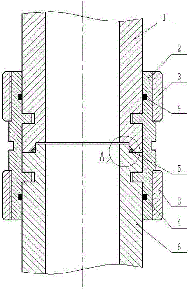
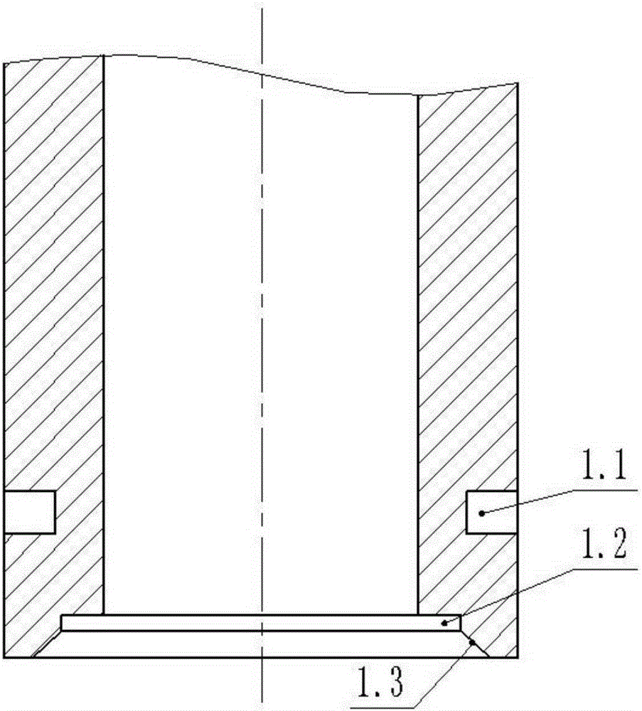
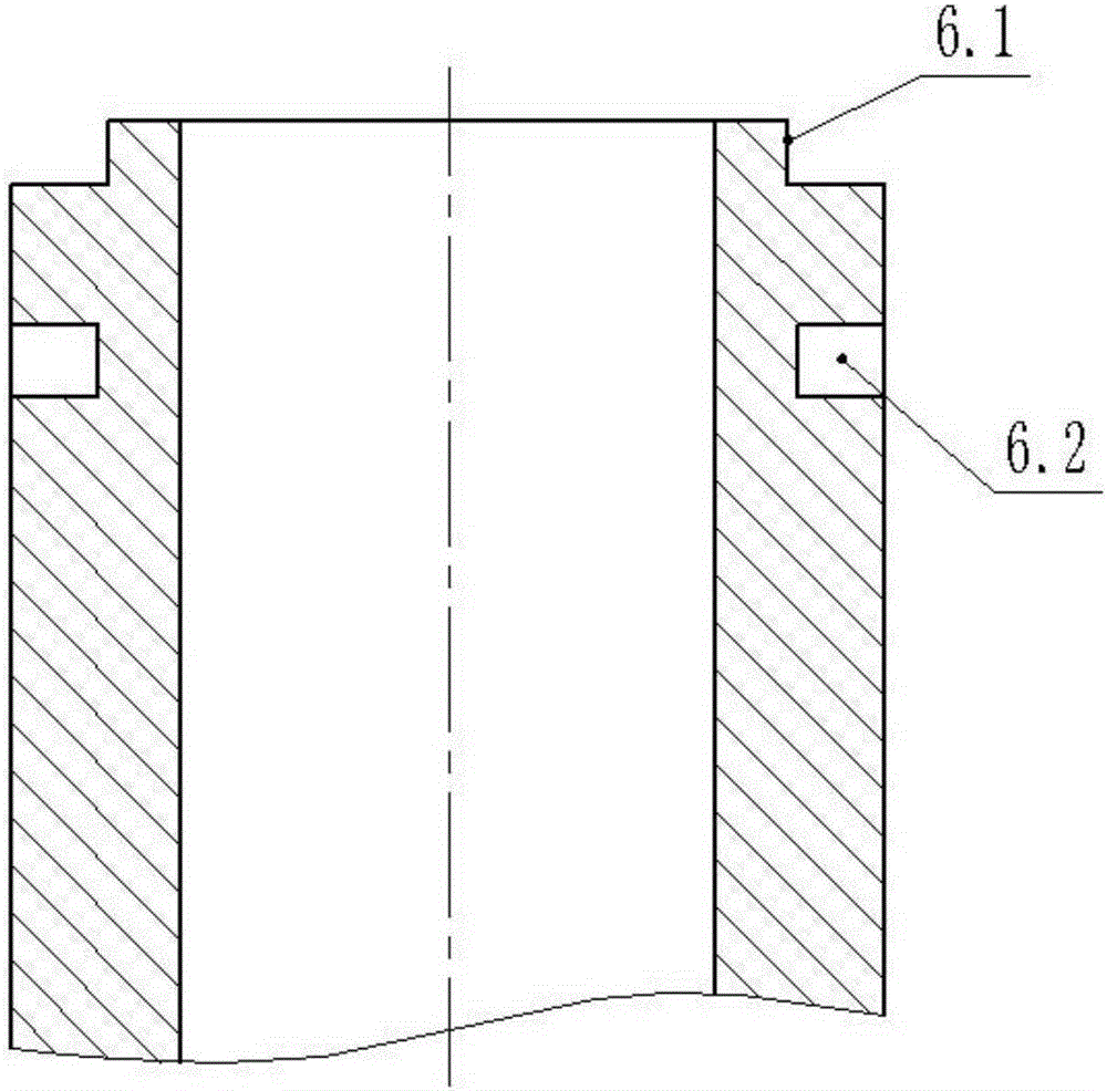
[0035] Such as Figure 1~6 As shown, a drill pipe joint provided by the present invention includes a male drill rod 1, a female drill rod 6, a snap ring 2 and a nut 3. The lower end of the male drill rod 1 is provided with an inner stop 1.2, and the inner The hole of the stop 1.2 is provided with a chamfer 1.3, the outer circumferential wall of the male drill rod 1 is provided with a groove 1.1, and the upper end surface of the female drill rod 6 is provided with an inner stop 1.2 of the male drill rod. With the mating outer stop 6.1, the circumferential outer wall of the female drill rod 6 is provided with a groove 6.2 that is the same as the male drill rod groove 1.1, the snap ring 2 has a vertical symmetric structure, and the snap ring 2 The outer circumferential wall is provided with two external threads, an undercut groove 2.3 is provided between the two outer threads, and the circumferential inner wall of the snap ring 2 is provided with a sealing groove 2...


PUM


Abstract

The invention discloses a drill rod connector which comprises a male drill rod, a female drill rod, a snap ring and nuts. An inner spigot is arranged on the lower end face of the male drill rod, chamfers are formed in orifices of the inner spigot, grooves are formed in the outer wall of the periphery of the male drill rod, an outer spigot matched with the inner spigot of the male drill rod is arranged on the upper end face of the female drill rod, grooves which are the same as those formed in the male drill rod are formed in the outer wall of the periphery of the female drill rod, two outer threads are formed in the outer wall of the periphery of the snap ring, the inner wall of the periphery of the snap ring is provided with sealing grooves and protruding blocks which are both symmetric up and down, the male drill rod is in location fit with the female drill rod through the inner spigot and the outer spigot, the snap ring is inserted into the grooves formed in the outer wall of the periphery of the male drill rod and the grooves formed in the outer wall of the periphery of the female drill rod through the protruding blocks, the male drill rod, the female drill rod and the snap ring are connected into a whole, and the two nuts are installed on the two outer threads of the outer wall of the periphery of the snap ring. The drill rod connector has the advantages of being reliable in sealing, capable of bearing forward and reverse rotating torque and convenient to assemble and disassemble.

Description

technical field [0001] The invention relates to the technical field of drilling, in particular to a drill pipe joint. Background technique [0002] Most of the existing drill pipe joints are threaded connections. The threaded connection method is to process one joint into an internal thread and a seam on the end face, and the other joint that is connected with it is processed into an external thread and a seam on the end face, and the drill pipe is driven by the power of the drilling rig to tighten the thread to connect the two sections of the drill pipe. After tightening, the spigot on the end face is in a tight fit state. In the same way, the drill rod is driven by the power of the drilling rig to unscrew the thread and the two sections of the drill rod are disassembled. [0003] The threaded connection method has the following disadvantages: a) The drill pipe with the threaded connection method can only implement forward rotation drilling operations, and the drill pipe ...

Claims


Application Information

Patent Timeline
IPC IPC(8): E21B17/046
Inventor 王睿黄建华
Owner CHTC JOVE HEAVY IND
Why Eureka
Try Eureka