
Turbine blade body structure

A turbine blade and airfoil technology, applied in the direction of blade support components, engine components, machines/engines, etc., can solve the problem of not considering secondary flow loss, turbine blade airfoil profile loss, and not considering secondary flow Loss and other issues, to achieve the effect of large-scale application and promotion, improve aerodynamic performance, and reduce lateral pressure gradient

Active Publication Date: 2016-02-03
DONGFANG TURBINE CO LTD
View PDF4 Cites 10 Cited by
  • Summary
  • Abstract
  • Description
  • Claims
  • Application Information

AI Technical Summary

Problems solved by technology

[0002] The airfoil shape of the existing turbine blades is mainly limited to the surface friction loss of the two-dimensional airfoil (the two-dimensional airfoil refers to the shape of the cross-sectional profile of the airfoil), that is, the profile loss, which is mainly considered It is the middle area of ​​the blade body of the turbine blade (that is, the main flow area), and does not consider the secondary flow loss
However, in the structure of the turbine blade, another main source of the loss of the turbine blade airfoil is the secondary flow loss in the airfoil end area (that is, the root area and the top area of ​​the turbine blade airfoil)
This turbine blade airfoil structure, which does not consider the secondary flow loss, has technical problems of low aerodynamic performance and high aerodynamic loss

Method used


Image

  • Turbine blade body structure
  • Turbine blade body structure
  • Turbine blade body structure

Examples


Embodiment Construction

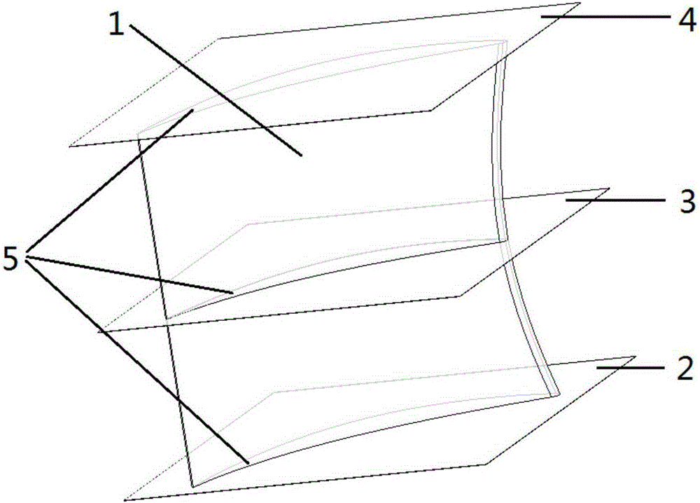
[0023] see figure 1 and figure 2 As shown, the present invention is an airfoil structure of a turbine blade. The airfoil of a turbine blade 1 is composed of a bottom-up root region 2, a middle region 3 and a top region 4, and each region has a matching two Dimensional airfoil 5, the two-dimensional airfoil refers to the shape of the cross-sectional profile of the airfoil.

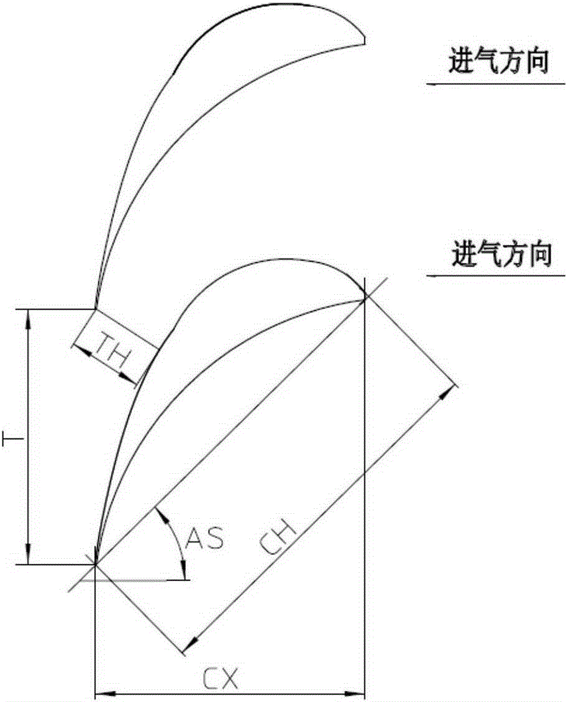
[0024] The two-dimensional airfoil 5 of the blade body of the turbine blade 1 is a crescent-shaped closed curve surrounded by the inner arc curve and the back arc curve, which has a characteristic parameter chord length CH (the small circle on the inlet and outlet sides of the two-dimensional airfoil shape In the direction of the common tangent line, the maximum width of the two-dimensional airfoil), the axial width CX (the maximum width of the two-dimensional airfoil in the air inlet direction), the pitch T (the distance between adjacent two-dimensional airfoils), and the throat width TH (minimum channe...


PUM


Abstract

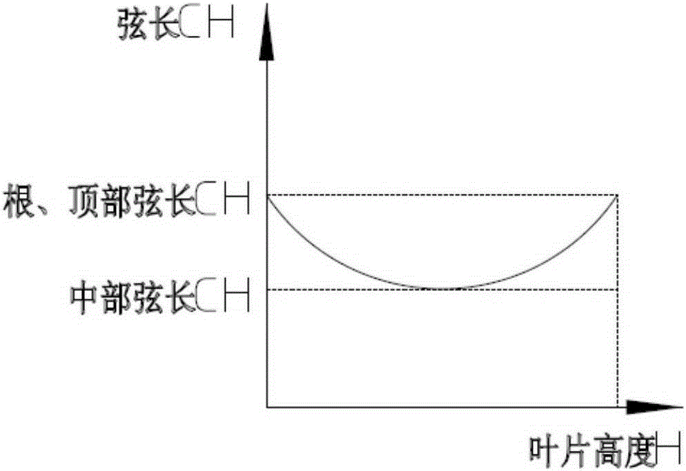
The invention discloses a turbine blade body structure. A two-dimension blade profile of a blade body is a crescent closed curve defined by an inner arc curve and a back arc curve; the blade body has a characteristic parameter chord length CH, and an axial width CX; the blade body is formed by twisting and superimposing multiple two-dimension blade profiles according to a certain rule, and has a characteristic parameter blade body height H; the chord length CH of the two-dimension blade profile accords with a parabolic distribution rule from the root area to the top area in the blade height direction; a trend is that the chord lengths of the root area and the top area of the blade body are high, and the chord length of the middle area of the blade body is low; and the axial width CX of the two-dimension blade profile substantially remains unchanged. The turbine blade body structure can allow the turbine blade to simultaneously give consideration to different main loss sources of the root area, the top area and the middle area, thereby effectively and reliably improving the aerodynamic performance of the turbine blade and reducing aerodynamic loss.

Description

technical field [0001] The invention relates to a turbine blade, in particular to a blade body structure of a turbine blade. Background technique [0002] The airfoil shape of the existing turbine blades is mainly limited to the surface friction loss of the two-dimensional airfoil (the two-dimensional airfoil refers to the shape of the cross-sectional profile of the airfoil), that is, the profile loss, which is mainly considered It is the middle area of ​​turbine blade airfoil (that is, the main flow area), and the secondary flow loss is not considered. However, in the structure of the turbine blade, another main source of the loss of the airfoil profile of the turbine blade is the secondary flow loss in the airfoil end area (ie, the root area and the top area of ​​the turbine blade airfoil). This turbine blade airfoil structure, which does not consider the secondary flow loss, has the technical problems of low aerodynamic performance and high aerodynamic loss. Contents o...

Claims


Application Information

Patent Timeline
Patent Type & Authority Applications(China)
IPC IPC(8): F01D5/14
Inventor 邓国梁范小平孙奇钟刚云张晓丹钟主海
Owner DONGFANG TURBINE CO LTD
Learn More