Brake device for a drive device of a robot

A technology of braking equipment and driving devices, applied in mechanical equipment, brake types, manipulators, etc., can solve problems such as material failure and high impact force, achieve rapid response behavior, improve service life, and avoid mechanical failures

Pending Publication Date: 2022-03-11
FRANKA EMIKA GMBH
View PDF9 Cites 0 Cited by
  • Summary
  • Abstract
  • Description
  • Claims
  • Application Information

AI Technical Summary

Problems solved by technology

However, due to the high rotational speeds, the impact forces between the head pin and the horn are so high that a very significant elastic deformation occurs which can cause the material of the horn to fail after a certain number of braking cycles

Method used


Image

  • Brake device for a drive device of a robot
  • Brake device for a drive device of a robot
  • Brake device for a drive device of a robot

Examples


Embodiment Construction

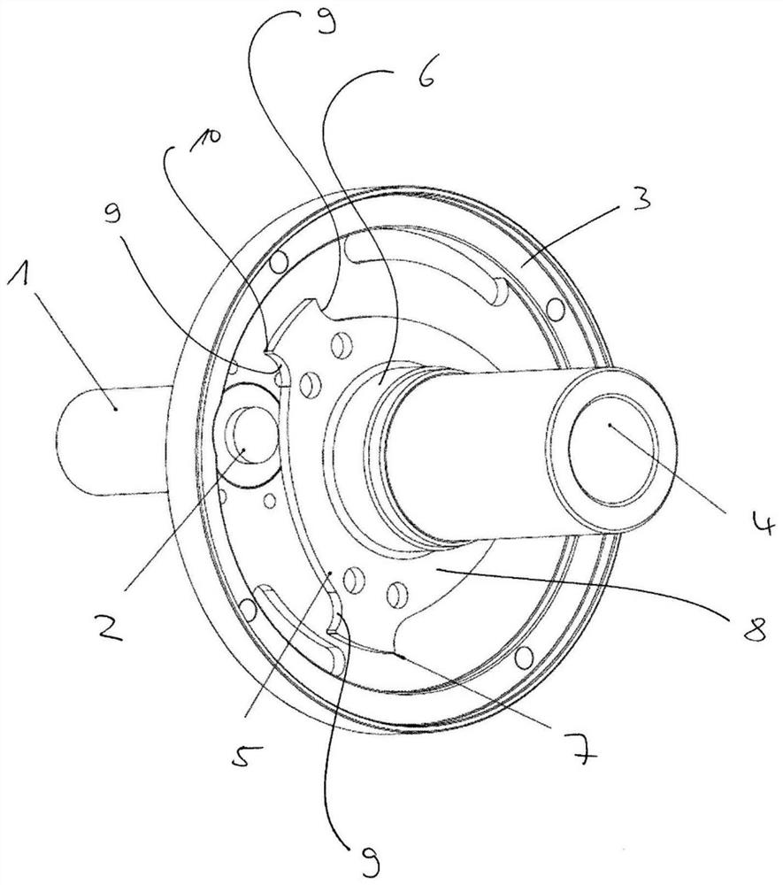
[0029] figure 1 The brake device according to the invention shown schematically in , can preferably be attached to one end of the drive of the joint between the two limbs of the robot arm.

[0030] The brake system according to the invention comprises a brake actuation device 1 which can be designed, for example, as a magnetically actuated holding or spring mechanism. The brake activation device 1 is designed and configured to activate a locking element in the form of a pin 2 when required, eg in the event of an unexpected power failure, whereby the pin 2 is driven upwards, eg by a spring.

[0031] By means of a bearing washer 3 fastened to the housing (ie connected to the housing of the drive, not shown), the shaft or rotor 4 of the drive can be supported via known bearings, not shown. The brake activation device 1 with the pin 2 is fixedly arranged on the bearing washer 3 .

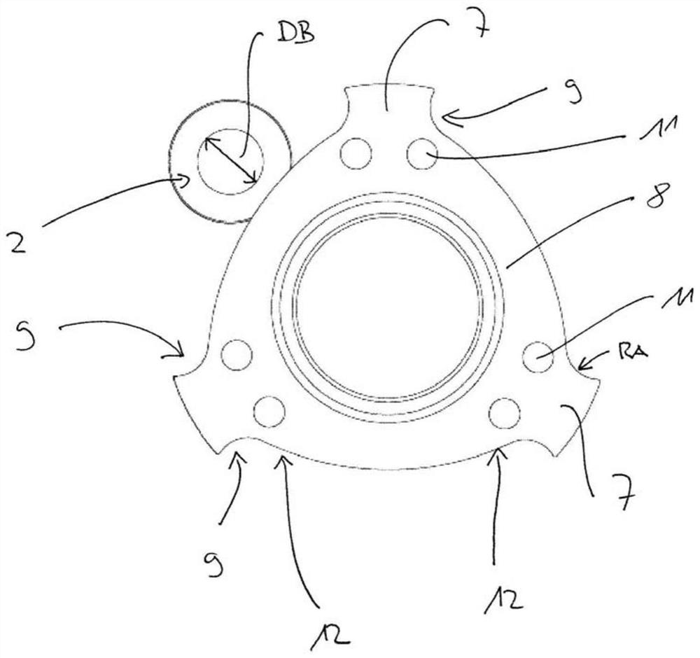
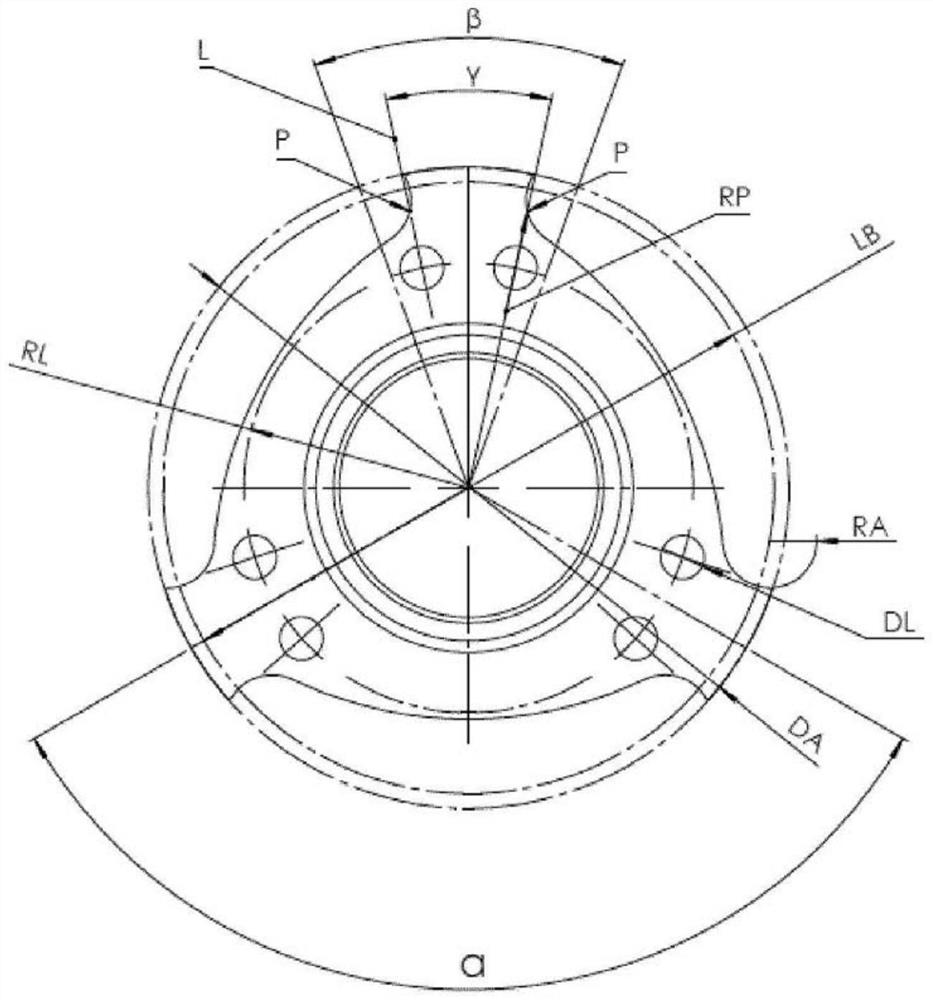
[0032] The rotor 4 carries a braking element in the form of a braking star 5 , which is connected ...


PUM


Abstract

The invention relates in particular to a braking device for a drive of a joint between two limbs of a robot arm, comprising a brake activation device (1) and a locking element (2), the brake activation device (1) being designed to engage the locking element (2), if necessary, with a rotor (4) of the drive in order to stop a rotation of the rotor (4), the locking element is designed as a pin (2), and the braking element is designed as a braking star wheel (5) having a web (7) with a defined impact surface (9) for the pin (2).

Description

technical field [0001] The invention relates to a braking device for a drive of a joint between two limbs of a robot arm or a manipulator, in particular a multi-axis articulated arm robot. Background technique [0002] In particular, for robots used in the field of human-robot collaboration (HRC), it is necessary for safety reasons to provide emergency stopping or braking equipment in the Stopping or braking devices are designed to stop the robotic arm as quickly as possible to prevent injury to the operator of the robotic system, or to prevent damage to objects manipulated by the robotic arm or to the robotic arm itself during activities the robotic arm is about to perform . Such an emergency stop can also be initiated directly by the user himself, for example by actuating an emergency switch. [0003] For example, various embodiments of braking devices for articulated arm robots are known, by means of which the movement of the robot arm can be stopped suddenly or at leas...

Claims


Application Information

Patent Timeline
Patent Type & Authority Applications(China)
IPC IPC(8): B25J19/00F16D63/00
CPCB25J19/0004F16D2125/38B25J17/00B25J9/106
Inventor 蒂姆·罗凯尔安德烈亚斯·斯宾纳卡莱斯·卡拉费尔·加西亚
Owner FRANKA EMIKA GMBH
Why Eureka
Try Eureka