A micro-vibration active vibration isolation device installation connector and installation method thereof

A technology of active vibration isolation and installation method, applied in non-rotational vibration suppression, building components, anti-vibration and other directions, can solve the problems of difficulty in leveling, restraint, waste, etc., and achieve the effect of easy operation

Active Publication Date: 2019-05-17
CHINA ELECTRONICS ENG DESIGN INST
View PDF6 Cites 0 Cited by
  • Summary
  • Abstract
  • Description
  • Claims
  • Application Information

AI Technical Summary

Problems solved by technology

[0002] At present, in the micro-vibration active control system, the active control device is directly installed and connected to the micro-vibration active control system. The installation and connection of the active control device cannot be disassembled. If there is a problem after completion, it can only be dismantled and rebuilt as a whole, which will cause serious damage to the project. In order to save inconvenience and waste, this problem is especially serious in the installation of controllers of various large-scale vibration control systems. In addition, various active vibration isolation devices will also cause various problems during the installation process due to their precision characteristics, such as difficult adjustment Level, height difference, constraint, and efficiency issues, etc.

Method used


Image

  • A micro-vibration active vibration isolation device installation connector and installation method thereof
  • A micro-vibration active vibration isolation device installation connector and installation method thereof
  • A micro-vibration active vibration isolation device installation connector and installation method thereof

Examples


Embodiment Construction

[0025] The present invention will be described in further detail below with reference to the accompanying drawings and specific embodiments, but it is not intended to limit the present invention.

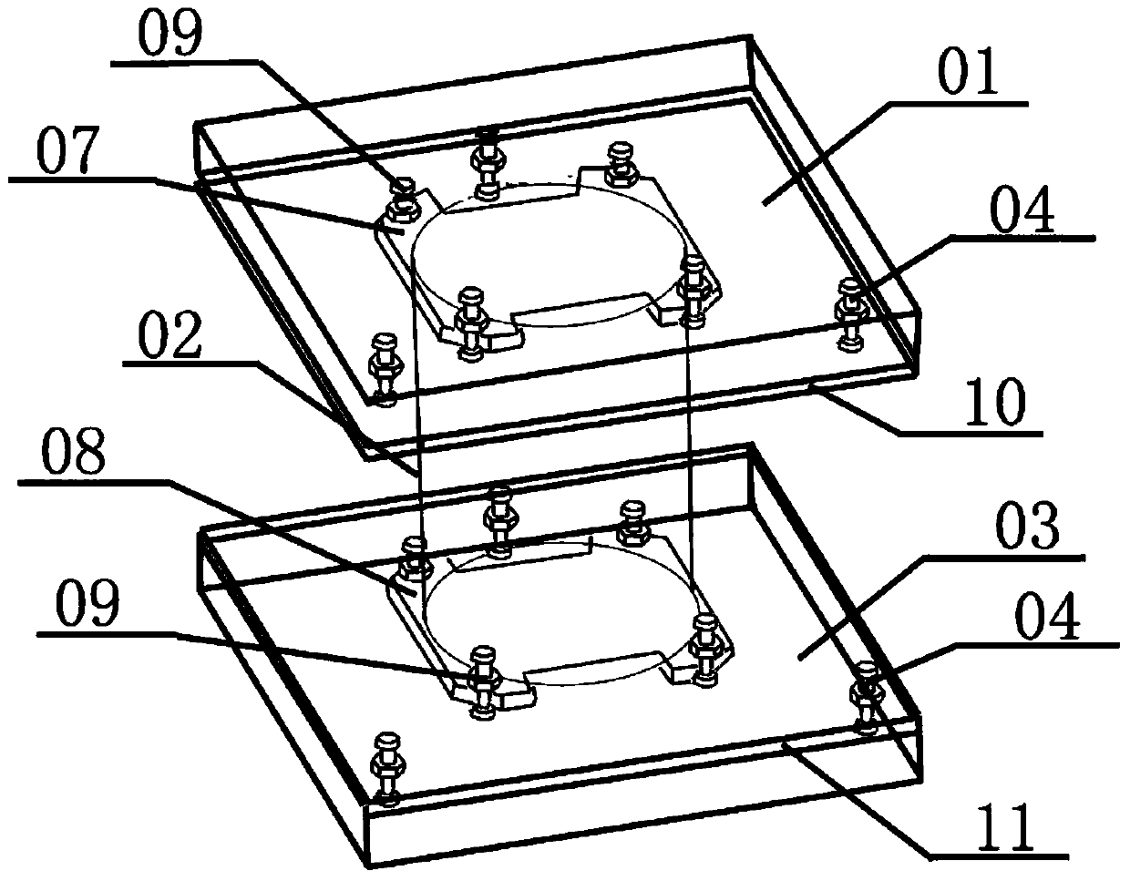
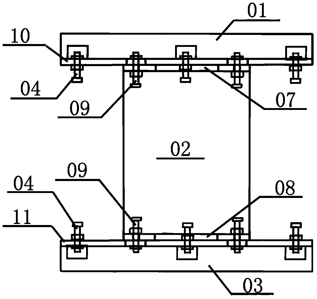
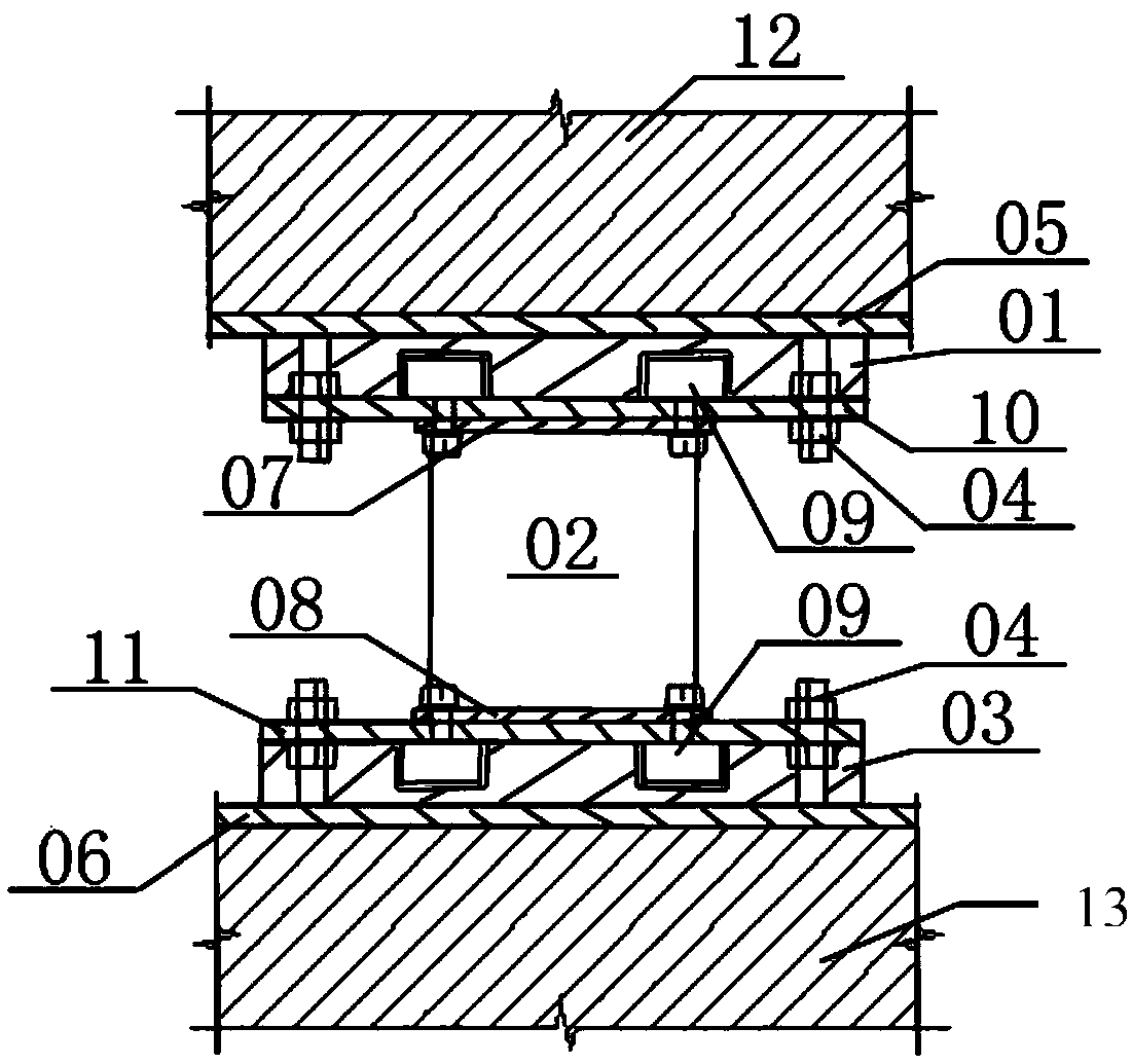
[0026] figure 1 It is a structural diagram of a mounting connector for a micro-vibration active vibration isolation device disclosed by the present invention, figure 2 It is a side view of a mounting connector for a micro-vibration active vibration isolation device disclosed by the present invention, as shown in figure 1 and figure 2 As shown, the present invention provides a micro-vibration active vibration isolation device installation connector, which includes from top to bottom: an upper glue filling tank 01, an active vibration isolation device 02 and a lower glue filling tank 03, image 3 It is a schematic diagram of the installation of a micro-vibration active vibration isolation device installation connector disclosed by the present invention, as shown in image 3 As sh...


PUM


Abstract

The invention discloses a mounting connecting part of a micro-vibration active vibration isolating device and a mounting method of the mounting connecting part. The mounting connecting part of the micro-vibration active vibration isolating device comprises an upper adhesive filling groove, an active vibration isolating device and a lower adhesive filling groove which are arranged from top to bottom in sequence, wherein the upper adhesive filling groove and the lower adhesive filling groove are filled with structural adhesive and are correspondingly fixedly welded to an upper embedded board and a lower embedded board through first regulating bolts; an upper bottom board and a lower bottom board of the active vibration isolating device are correspondingly fixedly welded to a low connecting plate of the upper adhesive filling groove and an upper connecting plate of the lower adhesive filling groove through second regulating bolts. According to the mounting connecting part of the micro-vibration active vibration isolating device, an upper embedded part and a lower embedded part are arranged, and the construction is carried out in manners of mounting, regulating, fixing and adhesive filling from bottom to top, so that the active vibration isolating device of any model in the micro-vibration active control system can be mounted and connected, and as a result, various problems caused by precision property in the mounting process of various active vibration isolating devices can be effectively solved.

Description

technical field [0001] The invention relates to an installation connector of a micro-vibration active vibration isolation device and an installation method thereof. Background technique [0002] At present, in the micro-vibration active control system, the active control device is directly installed and connected to the micro-vibration active control system. The installation and connection of the active control device cannot be disassembled. If there is a problem after completion, it can only be dismantled and rebuilt as a whole, which will cause serious damage to the project. In order to save inconvenience and waste, this problem is especially serious in the installation of controllers of various large-scale vibration control systems. In addition, various active vibration isolation devices will also cause various problems during the installation process due to their precision characteristics, such as difficult adjustment Level, height difference, constraint, and efficiency ...

Claims


Application Information

Patent Timeline
Patent Type & Authority Patents(China)
IPC IPC(8): F16F15/02E04B1/98
Inventor 陈骝胡明祎娄宇刘海宏窦硕俞渭雄夏艳李朝霞
Owner CHINA ELECTRONICS ENG DESIGN INST
Why Eureka
Try Eureka