
Liquid level seal connector and underwater connection signal transmission and air guide method thereof

A connector and liquid level technology, which is applied in the direction of connecting/disconnecting, connecting, and two-part connecting devices, etc., can solve the problem that the general connector cannot effectively seal the special cable for the liquid level transmitter and affect the liquid level transmitter Problems such as the range of use and accuracy, and the inability to communicate with the reference atmosphere, etc., to achieve the effects of repeated use, good sealing performance, and good sealing effect

Active Publication Date: 2016-02-03
MICRO SENSOR
View PDF8 Cites 3 Cited by
  • Summary
  • Abstract
  • Description
  • Claims
  • Application Information

AI Technical Summary

Problems solved by technology

Usually the sensing part of the transmitter is easily damaged, and the cost of some longer cables will exceed the transmitter itself
[0004] The sealing of the connector itself and the sealing of the special cable for the transmitter and ensuring the communication between the liquid level transmitter and the reference atmosphere are the difficulties of the liquid level sealing connector. At present, there is no connector specially used for the liquid level transmitter. , and the universal connector cannot effectively seal the special cable for the liquid level transmitter, and cannot communicate with the reference atmosphere, thus affecting the range of use and accuracy of the liquid level transmitter

Method used


Image

  • Liquid level seal connector and underwater connection signal transmission and air guide method thereof
  • Liquid level seal connector and underwater connection signal transmission and air guide method thereof
  • Liquid level seal connector and underwater connection signal transmission and air guide method thereof

Examples


Embodiment Construction

[0039] The present invention will be described in further detail below in conjunction with the accompanying drawings.

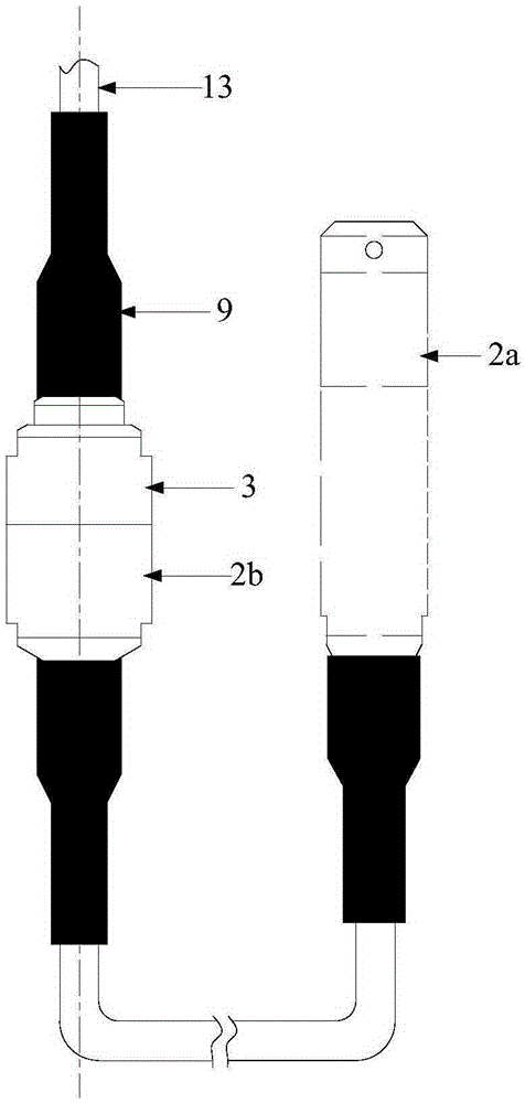
[0040] see Figure 1 to Figure 4 , The connector of the present invention includes two structures, one-piece and two-piece. Both the one-piece connector structure and the two-piece connector structure include a cable 13 and a shell cap; the two-piece connector structure also includes a connector shell.

[0041] Wherein in the one-piece connector structure, the sensor part of the transmitter can be connected with the shell cap part of the present invention, and the shell cap part can be directly connected to the signal receiving device and the power supply through the cable 13; in the split connector structure, the transmitter sensor The sense part is connected with the first shell cap part, the first shell cap part is connected with the connector shell part through the transmitter signal line, the connector shell part is connected with the second shell cap pa...


PUM


Abstract

The invention relates to a liquid level seal connector and an underwater connection signal transmission and air guide method thereof. The connector comprises a cable. One end of the cable is sleeved by a casing cap. The front end of the casing cap can be sleeved in a sensor casing body of a transmitter sensing part. A first sealing device is arranged at the joint of the casing cap and the sensor casing body. A second sealing device which is used for sealing the cable and the casing cap is arranged on the tail end of the casing cap. A plug of a connector is arranged in the casing cap. The plug is connected with the cable. The socket of the inserter is arranged in the sensor casing body and is connected with a transmitter signal line, so as to form an integral connector structure. According to the invention, the casing cap is sleeved in the sensor casing body; the transmitter sensing part, the cable and a power supply can be flexibly separated, which is convenient for replacement and maintenance; through first and second sealing devices, the casing cap and the sensor casing body are sealed to form a cavity; the cable, the plug and the socket are arranged in the cavity and are effectively isolated from an external medium; and the liquid level seal connector has the advantages of good sealing effect, high protection degree and great reliability.

Description

【Technical field】 [0001] The invention belongs to the technical field of transmitters, and relates to a liquid level sealing connector and a method for connecting and transmitting signals and conducting air under water. 【Background technique】 [0002] The liquid level sealed connector must be completely isolated from the external medium (such as water) after the assembly is completed, and the signal in the inner cavity of the connector is guaranteed to be transmitted safely and the sensor is connected to the reference atmosphere. The existing liquid level transmitter usually passes a special cable Connect the underwater sensing part with the above-water power supply and output part, and the special cable is inseparable from the sensor. [0003] For example, the transmitters usually used in hydropower stations need to use 200-500 meters of cables, and there are usually spare transmitters for emergencies, and there are also two transmitters in one position. Usually the sensin...

Claims


Application Information

Patent Timeline
Patent Type & Authority Applications(China)
IPC IPC(8): H01R13/52H01R24/00H01R43/26
Inventor 赵富荣杜舒鑫蔡亚平
Owner MICRO SENSOR
Learn More