Gas turbine combustor

A technology of gas turbines and burners, applied in combustion chambers, combustion methods, combustion equipment, etc., can solve problems such as shortened distances, narrow space for fuel nozzles, and inability to ensure sufficient space, and achieve the effects of improved accuracy and improved stability

Active Publication Date: 2016-02-10
MITSUBISHI POWER LTD
View PDF7 Cites 9 Cited by
  • Summary
  • Abstract
  • Description
  • Claims
  • Application Information

AI Technical Summary

Problems solved by technology

[0010] In the gas turbine combustor of the technology described in Patent Document 1, if the number of fuel nozzles is increased for the purpose of improving fuel dispersibility, the distance between fuel nozzles or the distance between fuel nozzles and nearby walls The subject of shortening the distance
[0011] Furthermore, if the distance between the fuel nozzles or the distance between the fuel nozzles and a nearby wall becomes shorter, the space around the fuel nozzles becomes narrower. In the gas turbine combustor of the technology described in Patent Document 2, if The fuel nozzle plate structurally supporting the fuel nozzle joins the ends of the fuel nozzles from the downstream side, and there is a problem that a sufficient space for joining cannot be ensured.

Method used


Image

  • Gas turbine combustor
  • Gas turbine combustor
  • Gas turbine combustor

Examples


Embodiment 1

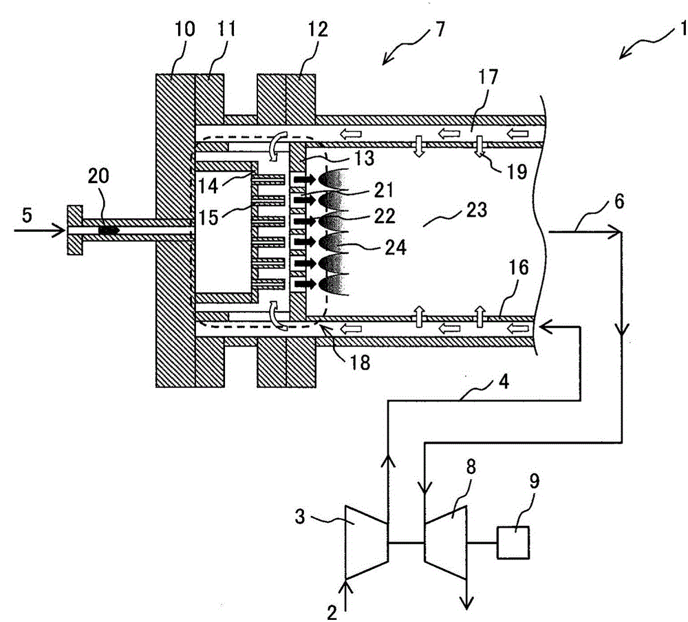
[0032] use figure 1 The structure of a gas turbine facility to which the gas turbine combustor according to Embodiment 1 of the present invention is applied will be described.

[0033] in application figure 1 In the gas turbine equipment 1 of the gas turbine combustor shown in Embodiment 1, the gas turbine equipment 1 includes: a compressor 3 that introduces air 2 from the atmosphere and compresses it; a gas turbine combustor 7 that compresses the air 2 compressed in the compressor 3 The compressed air 4 and the fuel 5 are combusted to generate high-temperature and high-pressure combustion gas 6; the turbine 8, which is driven by the combustion gas 6 generated by the gas turbine combustor 7, obtains the energy of the combustion gas 6 as rotational power; and the generator 9, It uses the rotational power of the turbine 8 to generate electricity.

[0034] The gas turbine combustor 7 includes an end cover 10 provided at the end of the gas turbine combustor 7 , a cylindrical fro...

Embodiment 2

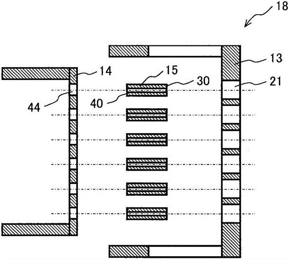
[0060] Next, use Figure 5 The partial enlarged view of the gas turbine combustor 7 according to the second embodiment of the present invention will describe the method of joining the fuel nozzle 15 constituting the burner 18 and the fuel nozzle plate 14 .

[0061] Figure 5 The partial enlarged view of the figure shows the details of the structure of the burner 18 provided on the gas turbine combustor 7 of Embodiment 2, which is different from the composition of the gas turbine combustor 7 of the embodiment 1 of the present invention described above. The basic structure of the joining method of the fuel nozzle 15 and the fuel nozzle plate 14 is similar, so the description of the same structure will be omitted, and the different parts will be described below.

[0062] Figure 5 The partial enlarged view of FIG. 2 shows that in the burner 18 of the gas turbine combustor 7 of the embodiment 2, the fuel nozzle 15 is engaged with the upstream side end 41 of the fuel nozzle plate...

Embodiment 3

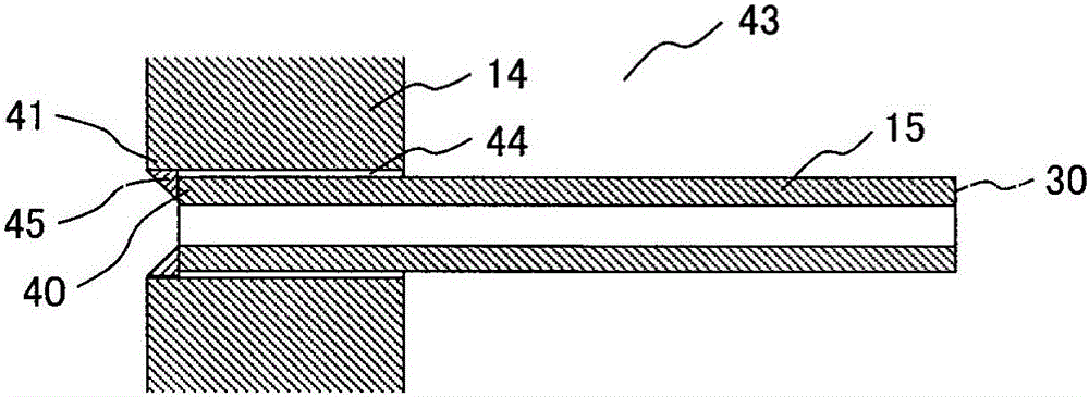
[0070] Next, use Figure 6 The partial enlarged view of the gas turbine combustor 7 according to the third embodiment of the present invention will describe the method of joining the fuel nozzle 15 constituting the burner 18 and the fuel nozzle plate 14 .

[0071] Figure 6 The partial enlarged view of the figure shows the details of the structure of the burner 18 in the gas turbine combustor of Embodiment 3, which is different from the fuel that constitutes the burner 18 of the gas turbine combustor 7 of the embodiment 1 of the present invention shown earlier. The basic structure of the joining method of the upstream end 40 of the nozzle 15 and the upstream end 41 of the fuel nozzle plate 14 is similar, so the description of the same structure will be omitted, and the different parts will be described below.

[0072] Figure 6 Details of the structure of the burner 18 in the gas turbine combustor 7 of the third embodiment are shown.

[0073] exist Figure 6 In the burner ...


PUM


Abstract

The invention provides a gas turbine combustor which can easily perform welding of fuel nozzles and a fuel nozzle plate and realize improvement of precision of welding of the fuel nozzles and the fuel nozzle plate even if the space around the fuel nozzles is narrow, thereby improving structural stability. The gas turbine combustor comprises a burner (18) including: a plurality of fuel nozzles (15) to supply a fuel (5); a fuel nozzle plate (14) to supports end portions of the fuel nozzles structurally and being configured to distribute the fuel flowing from an upstream side to the fuel nozzles; and a swirler (13) including a plurality of air holes (21) to supply combustion air, wherein the fuel nozzle plate is provided with a fuel nozzle receiving hole to receive the fuel nozzle, and the fuel nozzle plate and the fuel nozzle inserted in the fuel nozzle receiving hole are connected to each other from an upstream side of the fuel nozzle plate by welding.

Description

technical field [0001] The present invention relates to a gas turbine combustor, and more particularly to a gas turbine combustor provided with a fuel nozzle for injecting fuel. Background technique [0002] In gas turbine combustors, strict environmental standards are set for NOx emitted during gas turbine combustor operation in order to reduce the environmental load of exhaust gas. [0003] The emission of NOx increases as the temperature of the flame increases, so it is necessary to suppress the local formation of a high-temperature flame in the gas turbine combustor and achieve uniform combustion. [0004] In order to achieve uniform combustion in a gas turbine combustor, it is effective to improve the dispersion of fuel. For example, in the technology of a gas turbine combustor described in Japanese Patent Laid-Open No. A plurality of fuel nozzles are respectively arranged in the circumferential direction and the radial direction of the orifice plate, so as to improve ...

Claims


Application Information

Patent Timeline
Patent Type & Authority Applications(China)
IPC IPC(8): F23R3/28
CPCF23R3/283F23R2900/00018F23R3/286
Inventor 熊谷理和田山芳英苅宿充博百百聪八木宣夫
Owner MITSUBISHI POWER LTD
Why Eureka
Try Eureka