Supercharge Your Innovation With Domain-Expert AI Agents!

Method and apparatus for determining a stray magnetic field in the vicinity of a sensor

A sensor and leakage magnetic field technology, applied in the direction of instruments, measuring magnetic variables, measuring devices, etc., can solve problems such as angle errors

Active Publication Date: 2016-02-10
TDK MICRONAS GMBH
View PDF7 Cites 1 Cited by
  • Summary
  • Abstract
  • Description
  • Claims
  • Application Information

AI Technical Summary

Problems solved by technology

However, in the rotation angle measurement using a quadrupole magnet well known in the art, this interference due to leakage magnetic field can cause a maximum angle error of about 0.5 degrees

Method used


Image

  • Method and apparatus for determining a stray magnetic field in the vicinity of a sensor
  • Method and apparatus for determining a stray magnetic field in the vicinity of a sensor
  • Method and apparatus for determining a stray magnetic field in the vicinity of a sensor

Examples


Embodiment Construction

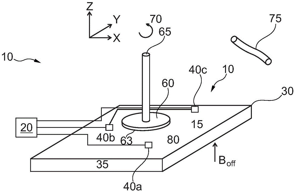
[0022] figure 1 An overview of a device 10 for determining stray magnetic fields in the vicinity of a sensor is shown. The device 10 has a disk-shaped permanent magnet 60 attached to an axle end 60 . The axle rotates about an axis of rotation 70 and the device 10 can measure the angle of rotation 15 of the axle.

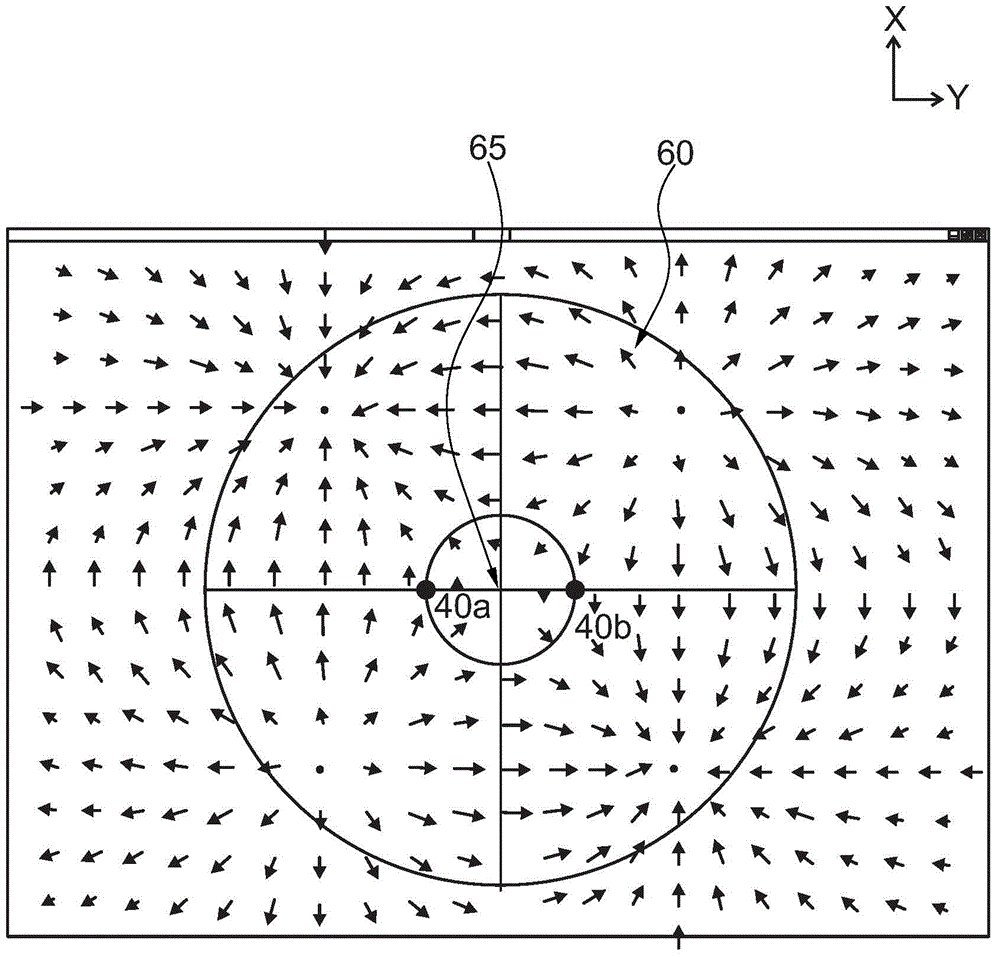
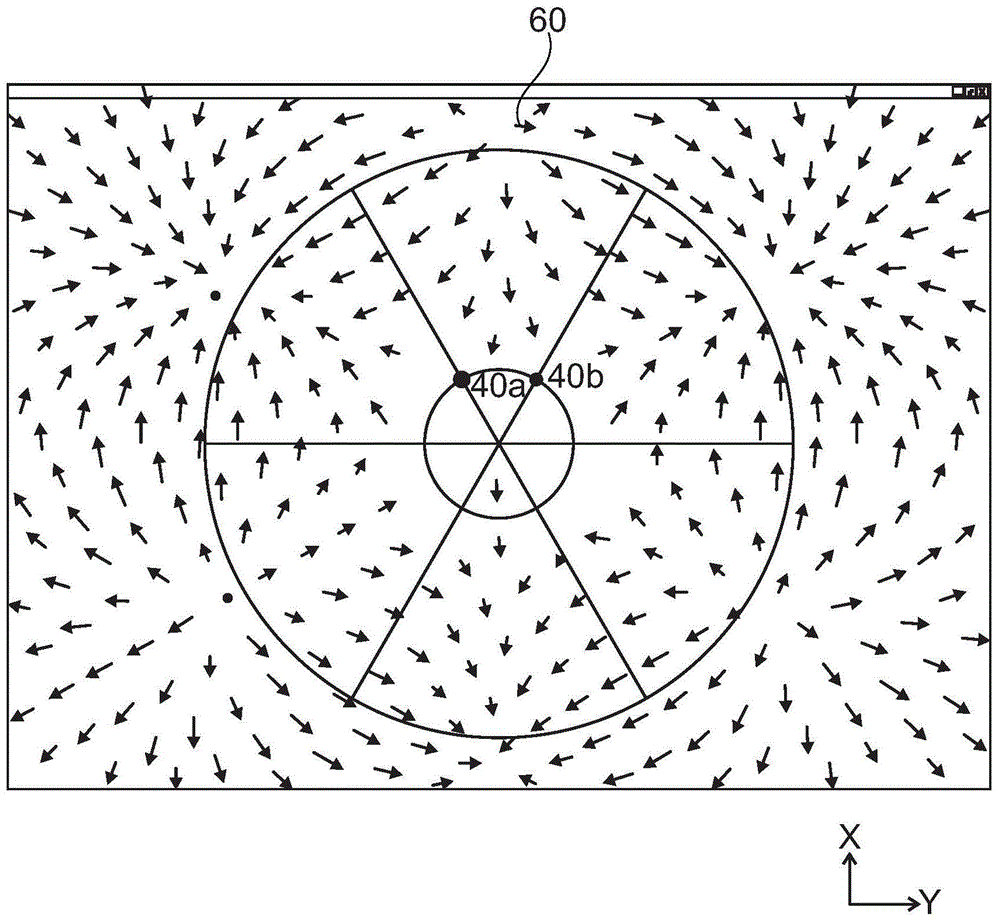
[0023] A semiconductor substrate 35, two pairs of vertical Hall sensors 40a and 40b are arranged equidistantly from the axis of rotation of the permanent magnet. The Hall sensors 40 a , 40 b measure the X and / or Y components of the magnetic field and are integrally integrated in the semiconductor substrate 35 . These vertical Hall sensors 40a and 40b are in figure 2 shown in more detail in and subsequently referred to in figure 2 Describe in detail. The circular path 50 is arranged in the chip plane 30 below the permanent magnet 60 . The axis of rotation 70 of the axle runs parallel to the Z direction through the center 55 of the circular path 50 and is arra...


PUM


Abstract

An apparatus (10) for determining a stray magnetic field in the vicinity of a sensor is described. The apparatus (10) has a multipole permanent magnet (60) with four or more poles and an axis of rotation (70). The multipole permanent magnet (60) produces a magnetic field (65) with magnetic field vectors (67). Two vertical Hall sensors (40a and 40) are so arranged in two positions on a circular path (50) about the axis of rotation, such that the sum of the magnet field vectors (67) measured at the two positions is substantially zero.

Description

[0001] Cross References to Related Applications [0002] This application claims the priority and benefit of German patent application DE102014110974.0 entitled "Method for reduing the influence of stray magnetic fields from current carrying conductor son systems for the measurement of angles using X / Y Hall sensors and permanent magnets", filed on August 1, 2014, the entire content of which is incorporated herein by reference. technical field [0003] The invention relates to a device and a method for determining a stray magnetic field in the vicinity of a sensor. Background technique [0004] Non-contact rotational angle measurement by means of the Hall effect is well known in the art. For example, from Reymond, S et al. published, "True2-DCMOSIntegratedHallSensor", IEEE Sensors 2007 Conference, pp. 860-863, a device for non-contact measurement of rotation angle is well known, this device has internally integrated 64 as a magnetic field The semiconductor substrate of the ...

Claims


Application Information

Patent Timeline
Patent Type & Authority Applications(China)
IPC IPC(8): G01R33/07
CPCG01R33/07
Inventor 罗尔夫·哈肯尼斯
Owner TDK MICRONAS GMBH
Features
  • R&D
  • Intellectual Property
  • Life Sciences
  • Materials
  • Tech Scout
  • Unparalleled Data Quality
  • Higher Quality Content
  • 60% Fewer Hallucinations
Learn More