Microstrip array antenna
A technology of microstrip array and antenna, applied in the direction of antenna, antenna coupling, antenna array, etc., can solve problems such as mutual coupling, achieve the effects of reducing radiation characteristics, avoiding grating lobes, and increasing beam scanning width
Active Publication Date: 2016-02-10
KUANG CHI INST OF ADVANCED TECH
View PDF7 Cites 21 Cited by
- Summary
- Abstract
- Description
- Claims
- Application Information
AI Technical Summary
Problems solved by technology
[0004] The present invention aims to provide a microstrip array antenna to solve t
Method used
View moreImage
Smart ImageViewing Examples
Examples
 PUM
 Abstract
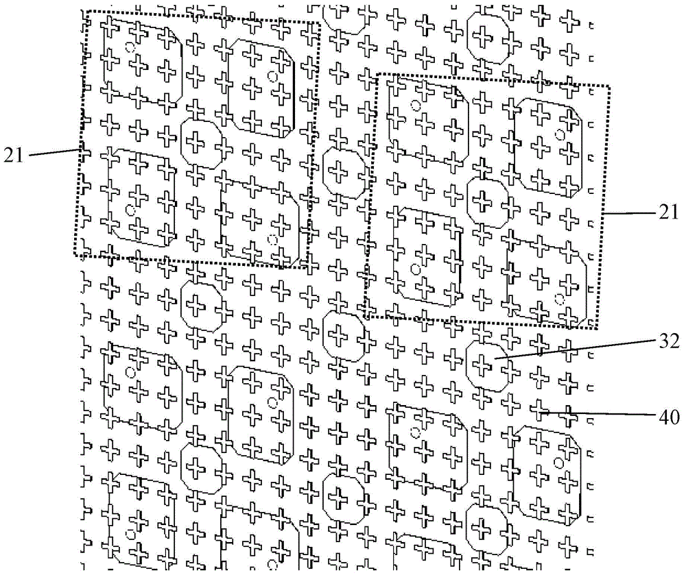
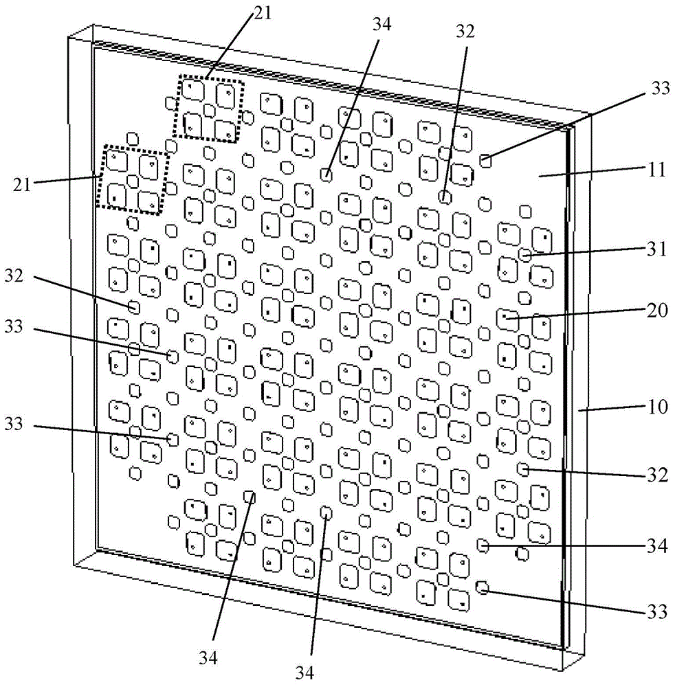
The invention relates to a microstrip array antenna. The microstrip array antenna includes a first dielectric substrate (10), a patch antenna (20) and parasitic patches; the first dielectric substrate (10) includes a first surface (11); the patch antenna (20) includes a plurality of patch antenna sub arrays (21) which are respectively arranged on the first surface (11), wherein each patch antenna sub array (21) includes a plurality of patch units; the parasitic patches are arranged on the first surface (11); the parasitic patches and the patch antenna (20) are located on the same plane; and the parasitic patches include first parasitic patches (31) which are located at the center of each patch antenna sub array (21). With the microstrip array antenna provided by the technical scheme of the invention adopted, the problem of mutual coupling between array units of a metal patch in the prior art can be effectively solved.
Description
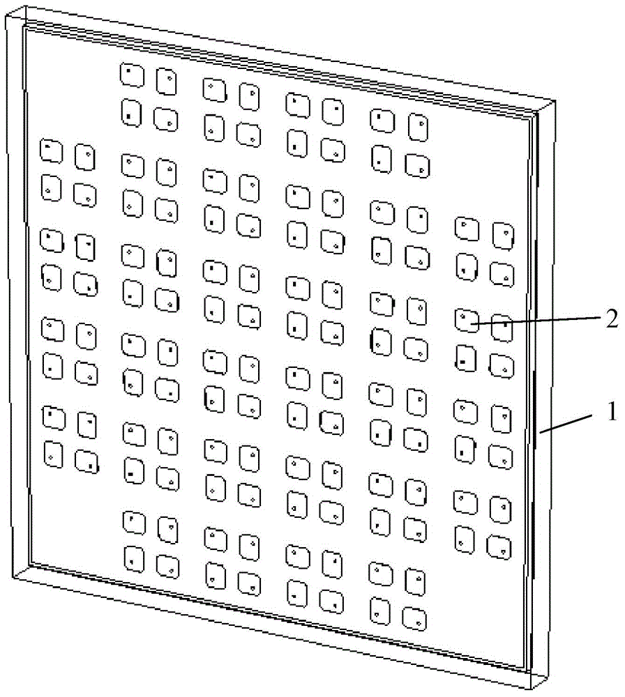
technical field [0001] The present invention relates to the technical field of antennas, in particular to a microstrip array antenna. Background technique [0002] Currently, if figure 1 As shown, the microstrip array antenna includes a dielectric substrate 1, a metal patch 2 and a ground plane. The metal patch 2 is arranged on the surface of the dielectric substrate 1, and the metal patches 2 are arranged in an array of 4×4 array units. There are many ways to achieve circular polarization for microstrip array antennas, figure 1 Circular polarization is achieved by rotating the metal patch in the 4×4 array unit by 90 degrees. The scanning angle of the microstrip array antenna is limited by various conditions such as the size of the metal patch 2, the material of the dielectric substrate 1, the number of array units, and T / R components. [0003] In the prior art, mutual coupling occurs between the array units of the metal patch 2 of the microstrip array antenna due to the ...
Claims
Login to View More Application Information
Patent Timeline
 IPC IPC(8): H01Q1/52H01Q21/00
Inventor 不公告发明人
Owner KUANG CHI INST OF ADVANCED TECH
Features
- R&D
- Intellectual Property
- Life Sciences
- Materials
- Tech Scout
- Unparalleled Data Quality
- Higher Quality Content
- 60% Fewer Hallucinations
Learn More Browse by: Latest US Patents, China's latest patents, Technical Efficacy Thesaurus, Application Domain, Technology Topic, Popular Technical Reports.
© 2025 PatSnap. All rights reserved.Legal|Privacy policy|Modern Slavery Act Transparency Statement|Sitemap|About US| Contact US: help@patsnap.com


