Coupled-feeding reconfigurable antenna and manufacturing method

A technology of coupling feeding and reconfiguring antennas, applied in the directions of antennas, antenna coupling, independent antenna unit combinations, etc., can solve the problems of reducing the working frequency band of high and low frequency antenna units, affecting the working performance of the antenna system, etc., to improve the working performance , the effect of reducing mutual coupling, improving radiation efficiency and gain

Active Publication Date: 2015-09-09
GUANGDONG OPPO MOBILE TELECOMM CORP LTD
View PDF5 Cites 20 Cited by
  • Summary
  • Abstract
  • Description
  • Claims
  • Application Information

AI Technical Summary

Problems solved by technology

With the large number of 4G mobile phones on the market, the existing antenna design scheme generally adopts the direct feeding scheme, through the RF switch (RF switch) to switch the first ground terminal or switch the matching circuit to change the resonant frequency of the high and low frequency bands at the same time, so as to cover the entire frequency band (low frequency 704-960MHz and high frequency 1710~2690MHz), since this sch

Method used


Image

  • Coupled-feeding reconfigurable antenna and manufacturing method
  • Coupled-feeding reconfigurable antenna and manufacturing method
  • Coupled-feeding reconfigurable antenna and manufacturing method

Examples


Example Embodiment

[0066] The following will clearly and completely describe the technical solutions in the embodiments of the present invention with reference to the accompanying drawings in the embodiments of the present invention. Obviously, the described embodiments are only some, not all, embodiments of the present invention. Based on the embodiments of the present invention, all other embodiments obtained by persons of ordinary skill in the art without making creative efforts belong to the protection scope of the present invention.

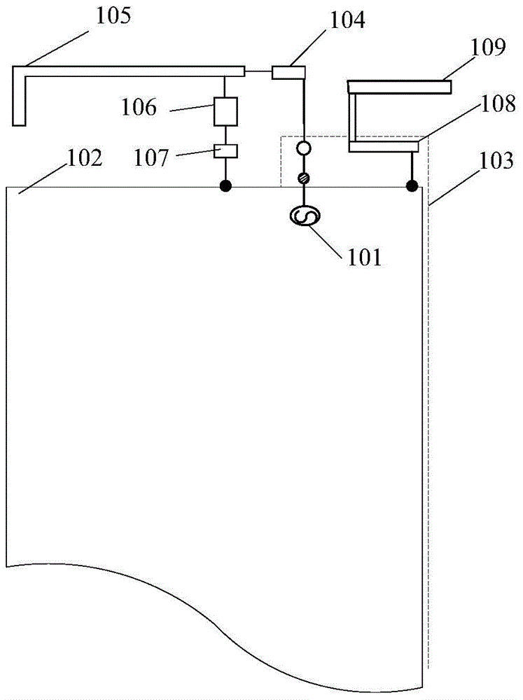
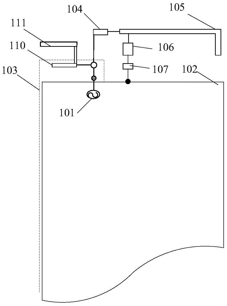
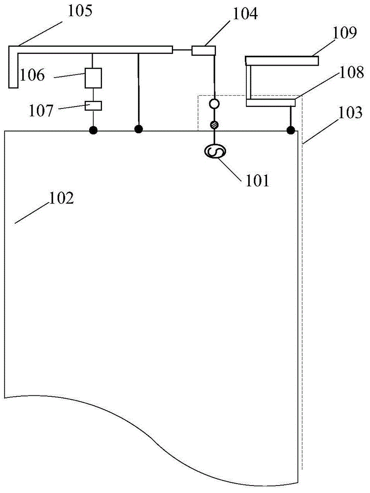
[0067] The invention discloses a coupled feeding reconfigurable antenna and a manufacturing method thereof. The high-frequency band resonant frequency is generated by transmitting energy through a coupling feeding capacitor, and the mutual coupling effect between high and low frequency antenna units is reduced through a low-pass filter to avoid adjustment. The influence of low frequency on high frequency avoids the influence of adjusting high frequency on low f...


PUM

PropertyMeasurementUnit
Resonant frequencyaaaaaaaaaa
Capacitanceaaaaaaaaaa
Thicknessaaaaaaaaaa

Abstract

The invention discloses a coupled-feeding reconfigurable antenna and a manufacturing method. The antenna comprises a feed source, a floor board, a dielectric plate, a low-pass filter, a low-frequency radiation unit, a radio-frequency switch, a first coupling sheet, a first high-frequency radiation unit, a second coupling sheet, and a second high-frequency radiation unit. The first side surface of the dielectric plate is provided with the first coupling sheet, and a feed point is connected with the feed source. The second side surface, opposite to first side surface of the dielectric plate, of the dielectric plate is provided with the second coupling sheet, wherein the second coupling sheet and the first coupling sheet are symmetric, and are equivalent to a coupling feed capacitor. The low-frequency radiation unit is disposed on the dielectric plate or a cellphone housing, and the low-pass filter is connected in series between a second contact of the low-frequency radiation unit and the feed point. The dielectric plate between the low-pass filter and the feed point is provided with a via hole. According to the embodiment of the invention, the antenna improves the radiation efficiency and gain of an antenna system, and finally improves the working performance of the antenna system.

Description

technical field [0001] The invention relates to the technical field of electronic circuits, in particular to a coupled feeding reconfigurable antenna and a manufacturing method. Background technique [0002] In antenna design, coupling technology refers to the fact that part of the patch of the antenna conducts electric energy to the metal patch that is not in contact with the surrounding but has a certain distance while being excited by the feed system, so that this part of the patch can be used without direct feeding. Can radiate electromagnetic waves. Feed means that the controlled device sends power to the control point. Coupling feed refers to the conduction of electric energy through coupling between two circuit elements or circuit networks that are not in contact but have a certain small distance in the field of communication, so that one of the elements does not conduct electric energy. The system gains energy when there is direct contact. Reconfigurable technolog...

Claims


Application Information

Patent Timeline
IPC IPC(8): H01Q1/38H01Q1/52H01Q5/10H01Q5/328H01Q5/335H01Q21/30
Inventor 曾元清
Owner GUANGDONG OPPO MOBILE TELECOMM CORP LTD
Why Eureka
Try Eureka