Antenna device for hearing instruments

A technology of antenna equipment and hearing aid equipment, which is applied in the direction of antenna, hearing aid, antenna coupling, etc., to achieve the effects of enhanced shielding effect, high emission magnetic field strength, and high receiving sensitivity

Active Publication Date: 2014-12-24
SIVANTOS PTE LTD
View PDF6 Cites 18 Cited by
  • Summary
  • Abstract
  • Description
  • Claims
  • Application Information

AI Technical Summary

Problems solved by technology

While it is possible to construct antennas more efficiently, this is generally only ensured by increasing the volume of the antenna

Method used


Image

  • Antenna device for hearing instruments
  • Antenna device for hearing instruments
  • Antenna device for hearing instruments

Examples


Embodiment Construction

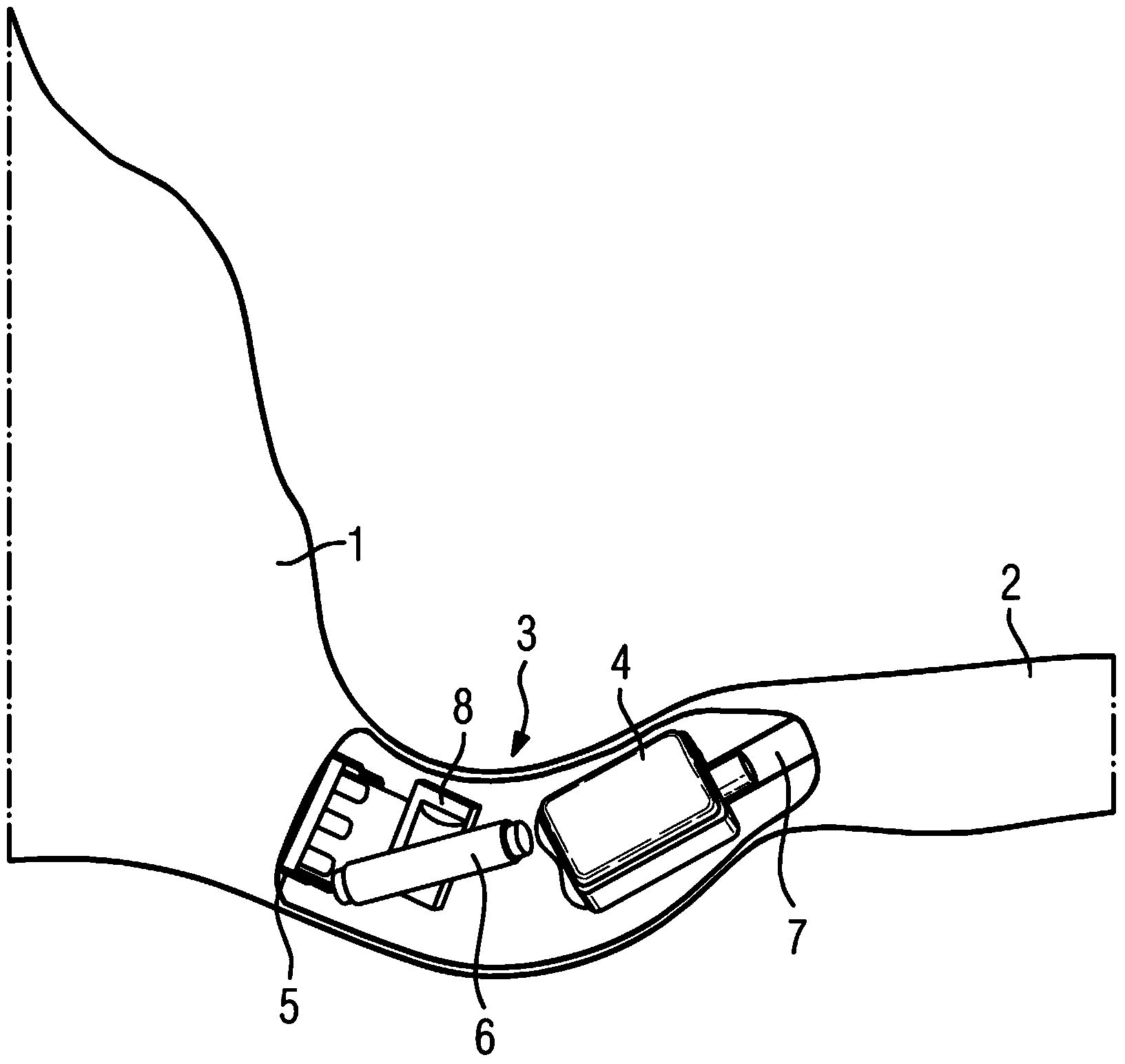
[0046] exist figure 1 The IDO hearing aid device in the prior art is schematically shown in . The IDO hearing aid device 3 is inserted into the external ear canal of the hearing aid wearer. It lies partly in the cartilaginous part 1 outside the ear canal and partly slides into the bony part 2 of the ear canal. Therefore, it is a deep ear canal hearing aid device.

[0047] In the hearing aid device 3 , the receiver 4 is arranged at the end oriented towards the eardrum. The receiver emits an acoustic signal via the acoustic channel 7 towards the eardrum. A hybrid circuit carrier 8 is provided on the panel arranged on the opposite end, which includes a signal processing device (not shown) and an amplifier for generating the control signals of the receiver 4 . The antenna 6 is likewise arranged on the panel 5 and is thus oriented in such a way that it is oriented in the direction of the opposite ear (not shown) of the wearer of the hearing aid device. The antenna 6 is used fo...


PUM


Abstract

Abstract Antenna device for hearing instruments The disclosure relates to an antenna device for hearing instruments, especially for hearing instruments to be worn in the auditory canal. A need exists specifying a hearing instrument, especially ITE hearing instrument having a data transmission system improved in respect of transmission bandwidth with no increase or only an insignificant increase in space and energy requirement. Disclosed an antenna device for a hearing instrument with an antenna arrangement (16) having a preferred send and receive spatial direction, and a further electrical hearing instrument component (13) which emits noise radiation predominantly in a noise radiation spatial direction. The antenna arrangement (16) and the further hearing instrument component (13) are disposed so that the send and receive spatial direction and the noise radiation spatial direction are oriented transverse to one another in such a way that a coupling-in of noise radiation into the antenna arrangement is reduced. The reduction of the noise couplings into the antenna arrangement makes possible a higher send and receive bandwidth, with the installation volume and energy requirement remaining the same. The further hearing instrument component can involve a receiver or any other component, especially one emitting inductive or electromagnetic radiation.

Description

technical field [0001] The invention relates to an antenna device for a hearing device, in particular for a hearing device to be worn in the ear canal. Background technique [0002] The hearing aid device can be designed, for example, as a hearing aid. Hearing aids are used to provide hearing-impaired people with ambient sound signals that are processed and enhanced in order to compensate or treat various hearing impairments. It basically consists of one or more input converters, signal processing means, amplification means and output converters. The input transducer is typically an acoustic receiver (eg a microphone) and / or an electromagnetic receiver (eg an induction coil). The output transducer is generally realized as an electro-acoustic transducer (such as a microspeaker) or an electromechanical transducer (such as a bone conduction earphone). It is also called a headset or receiver. The output transducer produces an output signal that is conducted to the ear of the...

Claims


Application Information

Patent Timeline
Patent Type & Authority Applications(China)
IPC IPC(8): H04R25/00H01Q1/22H01Q1/52
CPCH01Q1/273H01Q7/00H04R25/552H04R25/554H04R25/60H04R25/604H04R2225/025H04R2225/49H04R2225/51H04R25/609H04R2225/57H01Q1/22H04R25/55
Inventor P.尼克莱斯
Owner SIVANTOS PTE LTD
Why Eureka
Try Eureka