Multiple-input multiple-output (MIMO) antenna

a multi-input, multi-output technology, applied in the field of antennas, can solve problems such as degrading the performance of the antenna, and achieve the effects of improving isolation, increasing the directivity of the antenna, and reducing the amount of energy

Active Publication Date: 2016-08-18
GALTRONICS USA INC
View PDF4 Cites 17 Cited by
  • Summary
  • Abstract
  • Description
  • Claims
  • Application Information

AI Technical Summary

Benefits of technology

[0037]The MIMO antenna further includes at least one director 170. As seen in FIG. 1, each director 170 is L-shaped and located at a corner of the PCB 120 in the same plane as the ground layer. The director(s) 170 may be formed from a conductive material including, but not limited to, copper. The director(s) 170, like the ground stubs 150, improves the isolation between the antenna elements 110 adjacent to the respective director 170. The director 170 increases the directivity of the antenna by guiding, or directing, the electromagnetic waves that are radiating off of the corner stub 150 so that the electromagnetic waves continue propagating away from the corner of the PCB 120 thereby reducing the amount of energy that could otherwise propagate towards the adjacent antenna. As illustrated in the FIGS., there are two antenna elements proximate to each corner of the PCB 120. Both antenna elements 110 are directing the induced surface waves toward the corner of the PCB 120. Since the electrical length of the director is ½λ the surface waves induced by one antenna element 110 on the director will propagate (or radiate) away from the corner of the PCB 120 instead of propagating toward the adjacent antenna, thereby decreasing the mutual coupling between the two antenna elements 110.
[0038]As seen in FIGS. 1 and 5, the exemplary MIMO antenna 100 includes eight antenna elements 110 and eight corresponding antenna element mounting locations 130, two of the respective antenna elements 110 and two of the antenna element mounting locations 130 being on each side of the PCB 120. As seen in FIGS. 1 and 5, the antenna elements 110 are mounted towards the corners of the PCB 120. This allows the antenna elements 110 to be close to a, for example, 802.11ac radio port. This placement, reduces the distance between a radio port the and antenna elements 110 relative to other MIMO antennas which allows the MIMO antenna 100 to utilize printed transmission lines 400 to feed the antenna elements rather than more costly coaxial cables.

Problems solved by technology

However, when multiple antennas are mounted in close proximity, the antennas can interfere with one another, degrading the performance of the antennas.

Method used


Image

  • Multiple-input multiple-output (MIMO) antenna
  • Multiple-input multiple-output (MIMO) antenna
  • Multiple-input multiple-output (MIMO) antenna

Examples


Embodiment Construction

[0014]The following detailed description is merely exemplary in nature and is not intended to limit the invention or the application and uses of the invention. As used herein, the word “exemplary” means “serving as an example, instance, or illustration.” Thus, any embodiment described herein as “exemplary” is not necessarily to be construed as preferred or advantageous over other embodiments. All of the embodiments described herein are exemplary embodiments provided to enable persons skilled in the art to make or use the invention and not to limit the scope of the invention which is defined by the claims. Furthermore, there is no intention to be bound by any expressed or implied theory presented in the preceding technical field, background, brief summary, or detail of the following detailed description.

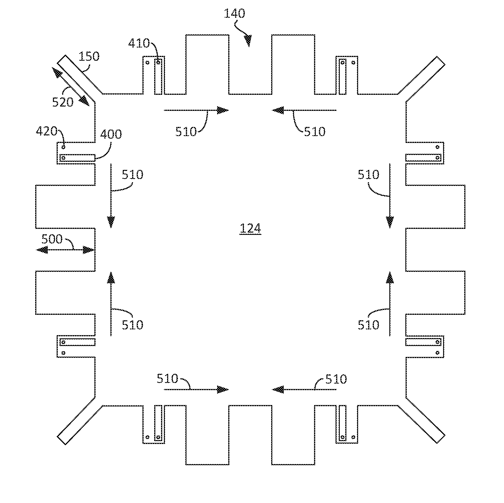
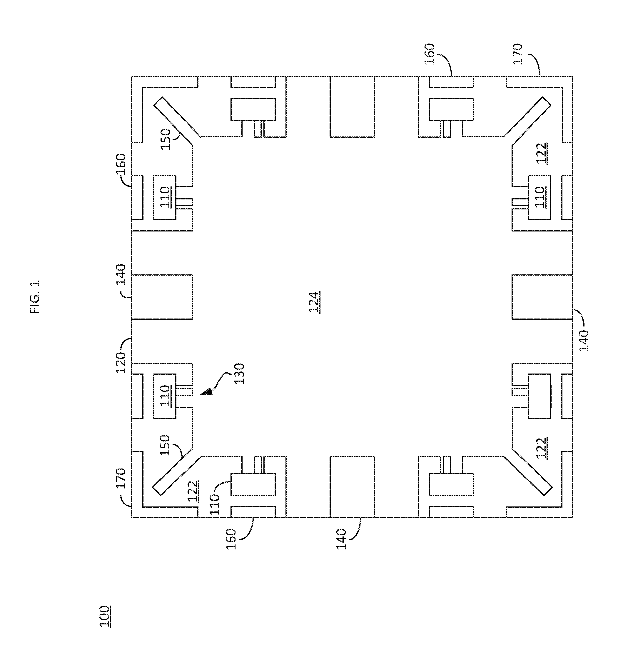
[0015]FIG. 1 illustrates an exemplary embedded MIMO antenna 100, in accordance with an embodiment. The multiple-input multiple-output (MIMO) antenna 100 utilizes multiple antenna elem...


PUM


Abstract

A multiple input multiple output (MIMO) antenna is provided. The MIMO antenna may include, but is not limited to, a printed circuit board having a plurality of edges and a ground layer including, but not limited to a plurality of antenna element mounting locations, at least one of the plurality of antenna element mounting locations being arranged on a first side of the printed circuit board and at least one of the plurality of antenna element mounting locations being arranged on a second side of the printed circuit board, a plurality of slots, each of the plurality of slots extending a predetermined distance from an edge of the printed circuit board, and at least one ground stub, the at least one ground stub comprising an extension of the ground layer of a predetermined electrical length at a predetermined angle relative to the edge of the printed circuit board.

Description

CROSS-REFERENCE TO RELATED APPLICATION(S)[0001]This application claims the benefit of U.S. provisional patent application Ser. No. 62 / 115,202 filed Feb. 12, 2015, the entire content of which is incorporated by reference herein.TECHNICAL FIELD[0002]The present disclosure generally relates to antenna, and more particularly relates to multiple input multiple output antenna.BACKGROUND[0003]Modern devices, such as Wi-Fi routers, often utilize multiple antennas to improve a throughput of the device. However, when multiple antennas are mounted in close proximity, the antennas can interfere with one another, degrading the performance of the antennas.BRIEF SUMMARY[0004]In one embodiment, for example a multiple-input multiple-output antenna is provided. The multiple-input multiple-output antenna may include, but is not limited to, a printed circuit board having a plurality of edges, the printed circuit board comprising a ground layer. The ground layer may include, but is not limited to, a plu...

Claims


Application Information

Patent Timeline
Patent Type & Authority Applications(United States)
IPC IPC(8): H01Q21/00H01Q15/00H01Q1/48H01P5/10H01Q9/16H01Q1/12
CPCH01Q21/0075H01Q9/16H01Q15/00H01Q1/48H01P5/10H01Q1/12H01Q1/521H01Q9/285H01Q19/24H01Q21/28
Inventor COZZOLINO, RANDELL
Owner GALTRONICS USA INC
Why Eureka
Try Eureka