The structure of the test box

A detection box and detection light technology, applied in the field of optical communication, can solve the problems of insufficient rigidity, short service life, and small amount of detection at one time, and achieve the effects of long service life, reasonable layout and compact structure

Active Publication Date: 2018-01-30
ZHEJIANG HUAXIN IND
View PDF6 Cites 0 Cited by
  • Summary
  • Abstract
  • Description
  • Claims
  • Application Information

AI Technical Summary

Problems solved by technology

[0002] As a modern communication technology, optical communication is receiving more and more attention. The performance of the core working unit of optical communication directly affects the quality of optical communication. Therefore, the existing core working unit of optical communication needs to be tested before application. The test and detection described above is usually carried out by installing the core working unit of optical communication in the test and detection box, but the current test and detection box has the disadvantages of small amount of detection at one time, insufficient rigidity, and short service life

Method used


Image

  • The structure of the test box
  • The structure of the test box
  • The structure of the test box

Examples


Embodiment Construction

[0017] The technical solutions of the present invention will be further specifically described below through the embodiments and in conjunction with the accompanying drawings.

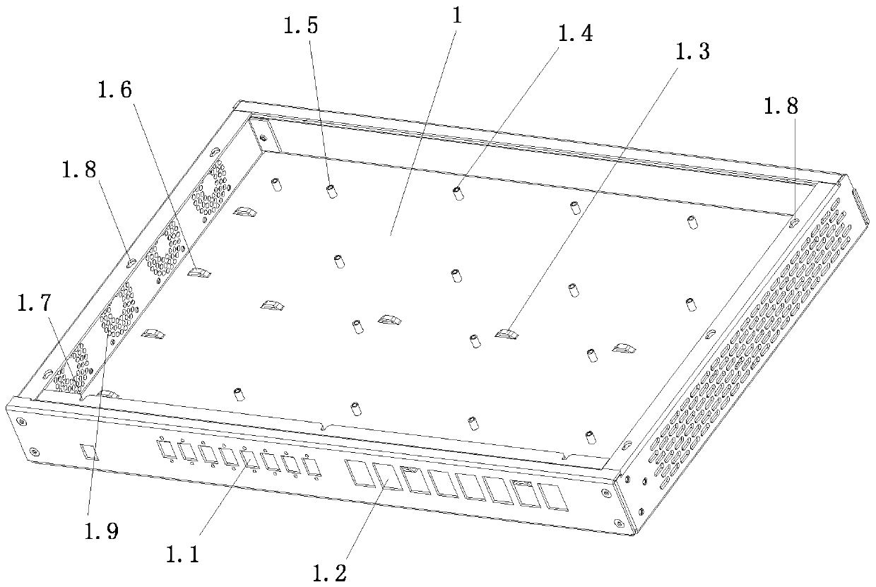
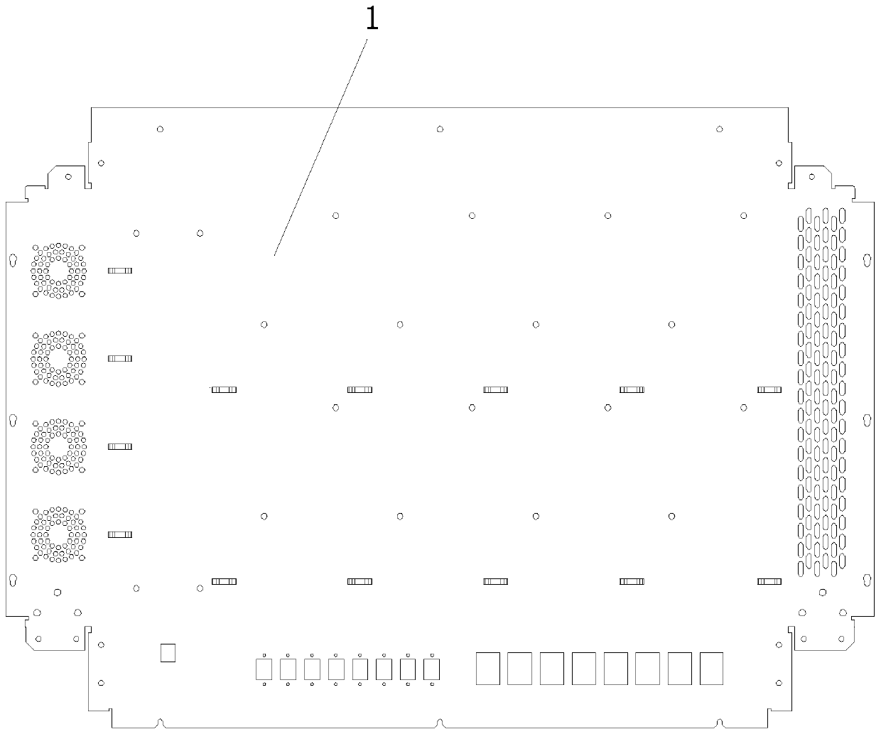
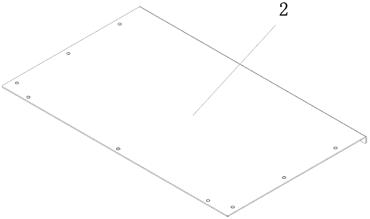
[0018] Such as figure 1 , figure 2 , image 3 , Figure 4 and Figure 5 As shown, the present invention includes a box body 1 and a box cover 2 . The box body 1 is bent into a drawer shape by bending steel plates; the upper end of the front side wall of the box body 1 is bent backward at 90° for the first time, then bent at 90° downward, and finally at 90° backward for the second time. Bending; the upper ends of the rear, left and right side walls of the box body 1 are bent inwardly at 90° at the same time, and the front and rear ends of the left and right sidewalls are bent inwardly at 90° and fixed to the front and rear sidewalls of the box body 1 respectively. Connect; the inward 90° bending of the rear, left and right side walls of the box body 1 is flush with the second 90° backward bending ...


PUM


Abstract

The invention relates to a structure of a test detection box. The structure comprises a box body and a box cover; the upper end of the front side wall of the box body is sequentially bended backwards, downwards and backwards by 90 DEG for three times; the upper ends of the rear, left and right side walls of the box body are simultaneously bended inwardly by 90 DEG; the front and rear ends of the left and right side walls are bended inwardly by 90 DEG and fixedly connected with the front and rear side walls of the box body respectively; the inward bending positions of the rear, left and right side walls of the box body are aligned to the second-time backward bending position of the box body; openings respectively used for fixing connection ports of PON ports and GE photoelectric multiplexing ports are arranged on the front side wall of the box body; a heat dissipation fan installation part and a heat dissipation hole are respectively arranged on the left and right side walls; installation parts of optical communication core working units to be tested and detected are arranged at the bottom of the box body; the rear end of the box cover is downwardly folded; the front, left and right ends of the box cover are movably connected with the second-time backwardly bended edge of the front side wall of the box body and the inwardly bended edges of the left and right side walls respectively; and the downwardly folded edge at the rear end of the box cover is in threaded connection with the rear side wall of the box body.

Description

technical field [0001] The invention relates to the field of optical communication, in particular to a structure of a test detection box for testing the performance of a core working unit of optical communication. Background technique [0002] As a modern communication technology, optical communication is receiving more and more attention. The performance of the core working unit of optical communication directly affects the quality of optical communication. Therefore, the existing core working unit of optical communication needs to be tested before application. The above test is usually carried out by installing the optical communication core working unit in the test box, but the current test box has the disadvantages of small amount of detection at one time, insufficient rigidity, and short service life. Contents of the invention [0003] The main purpose of the invention is to provide a test box with high rigidity and long service life for testing the performance of the...

Claims


Application Information

Patent Timeline
Patent Type & Authority Patents(China)
IPC IPC(8): H04B10/07
Inventor 陈祥鑫
Owner ZHEJIANG HUAXIN IND
Why Eureka
Try Eureka