
Scene motion correction in fused image systems

A technology for fusing images and images, which is applied to TV system components, image enhancement, image analysis, etc., and can solve problems such as frame jumping and aggravating lens shake

Active Publication Date: 2016-02-10
APPLE INC
View PDF4 Cites 13 Cited by
  • Summary
  • Abstract
  • Description
  • Claims
  • Application Information

AI Technical Summary

Problems solved by technology

For video cameras, camera shake can cause visible frame jumps in recorded video
In astronomical installations, changes in the atmosphere that can cause the apparent position of objects to change over time can exacerbate lens shake problems

Method used


Image

  • Scene motion correction in fused image systems
  • Scene motion correction in fused image systems
  • Scene motion correction in fused image systems

Examples


Embodiment Construction

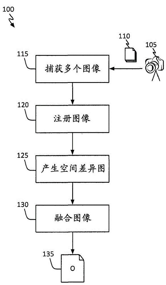
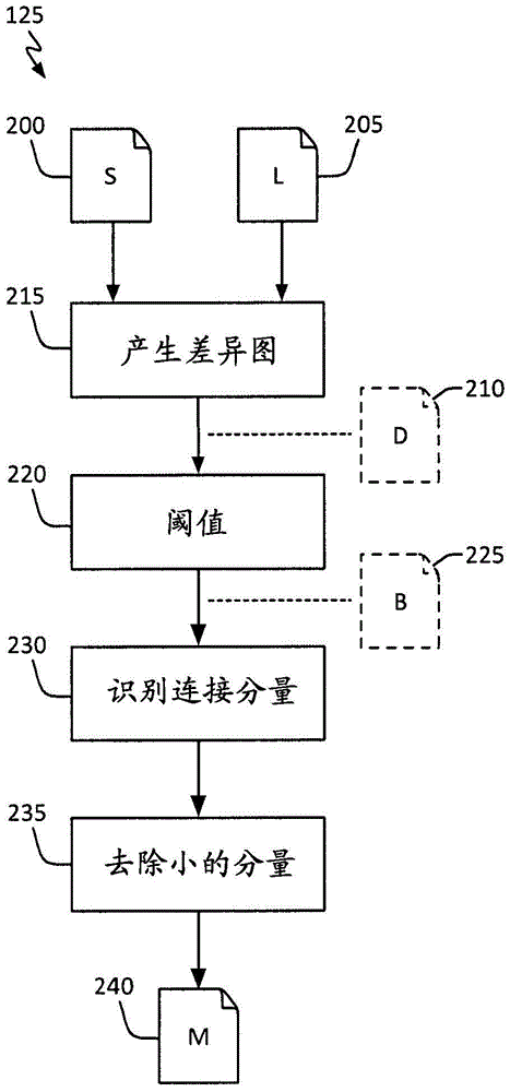
[0019] The present disclosure relates to systems, methods, and computer-readable media for improving image capture operations of stabilized image capture devices. In general, techniques are disclosed for capturing and fusing short and long exposure images of a scene by a stabilized image capture device. More specifically, the techniques disclosed in this paper not only use the individual pixel differences between the co-captured short-exposure and long-exposure images (like the state-of-the-art disparity map), but also use the Spatial structure of occluded regions. A new means of representing this feature is the "spatial difference map". The spatial difference map can be used to identify pixels in the short and long exposure images for fusion and, in one embodiment, can be used to identify short exposure images that can be filtered to reduce visual discontinuities (blurring) in the final output image of pixels. As used herein, the terms "digital image capture device," "imag...


PUM


Abstract

The invention relates to scene motion correction in fused image systems. Techniques to capture and fuse short- and long-exposure images of a scene from a stabilized image capture device are disclosed. More particularly, the disclosed techniques use not only individual pixel differences between co-captured short- and long-exposure images, but also the spatial structure of occluded regions in the long-exposure images [e.g., areas of the long-exposure image(s) exhibiting blur due to scene object motion). A novel device used to represent this feature of the long-exposure image is a "spatial difference map." Spatial difference maps may be used to identify pixels in the short-and long-exposure images for fusion and, in one embodiment, may be used to identify pixels from the short-exposure image(s) to filter post-fusion so as to reduce visual discontinuities in the output image.

Description

technical field [0001] The present disclosure relates to scene motion correction in fused image systems. Background technique [0002] This broad class of techniques that involves reducing image blur associated with camera motion may be referred to as "image stabilization." In fact, the main goal of image stabilization is to reduce camera shake caused by the photographer's inability to eliminate their hand movements during image capture. Image stabilization is available for binoculars, still and video cameras, and astronomical telescopes. In still cameras, camera shake can be especially problematic with slow shutter speeds or long focal length (telephoto) lenses. With video cameras, camera shake can cause frame jumps that are visible in recorded video. In astronomical installations, changes in the atmosphere that can cause the apparent position of objects to change over time can exacerbate lens shake problems. [0003] Image stabilization may be provided, for example, by...

Claims


Application Information

Patent Timeline
IPC IPC(8): H04N5/217
CPCG06T5/50G06T7/254G06T2207/10144G06T2207/20221H04N23/80H04N23/743H04N23/741H04N25/589G06T5/73G06T5/70H04N23/951H04N23/957G06T11/60H04N5/91G06T2207/10004H04N23/6845H04N23/683H04N23/6811H04N25/626G06T7/20
Inventor C·莫尔加德M·蒂考R·托伏特P·M·胡渤
Owner APPLE INC
Learn More