
Method and apparatus for motion invariant imaging

Active Publication Date: 2009-10-01
MASSACHUSETTS INST OF TECH
View PDF5 Cites 70 Cited by
  • Summary
  • Abstract
  • Description
  • Claims
  • Application Information

AI Technical Summary

Benefits of technology

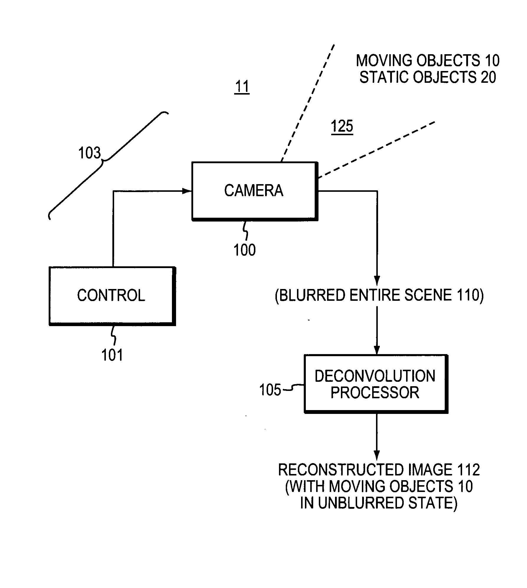
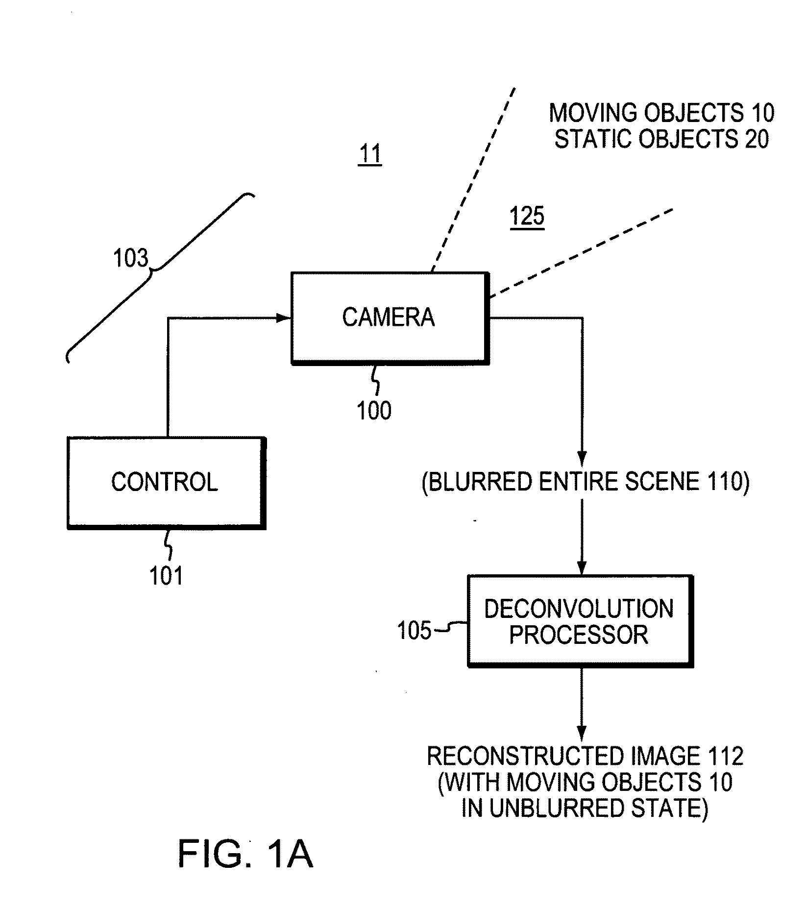
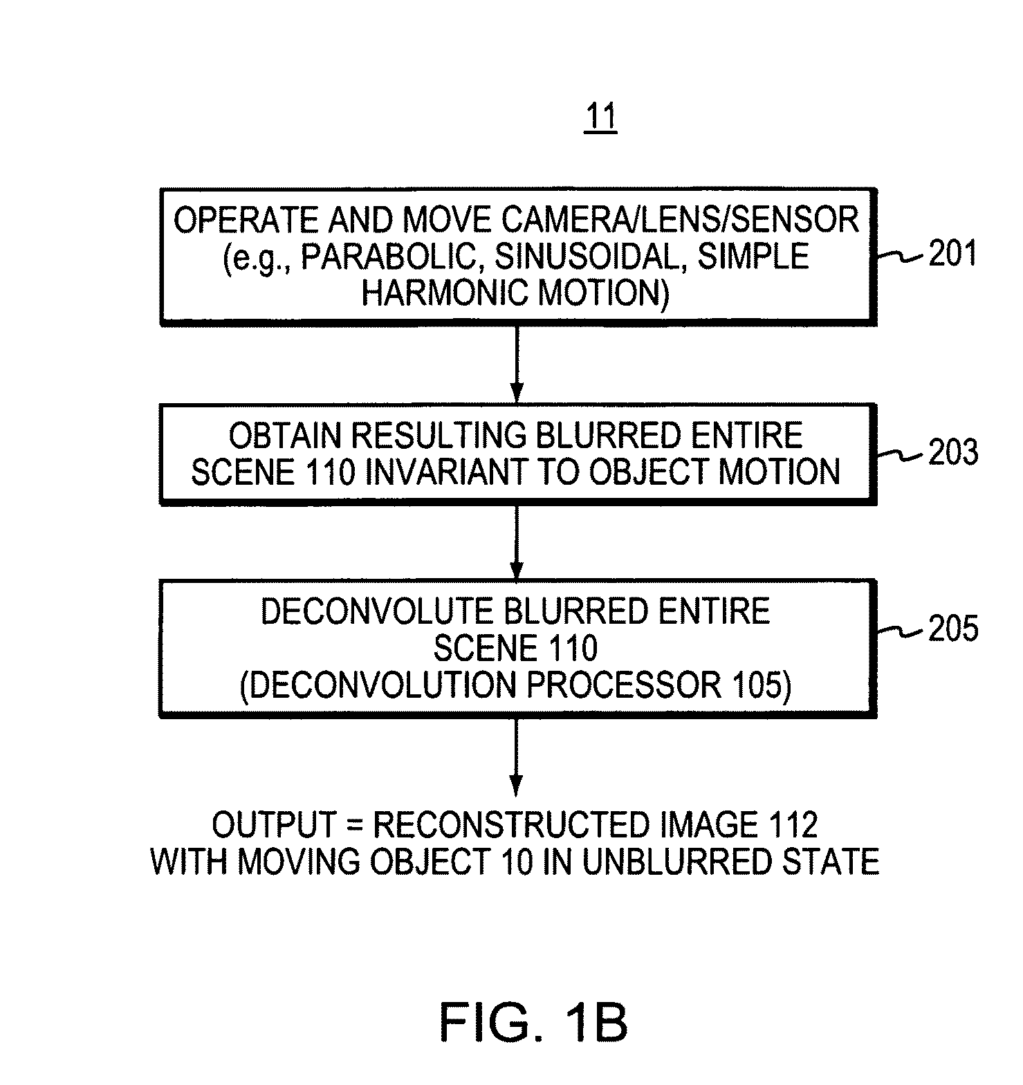
[0009]The present invention addresses the foregoing problems in the art. In the present invention, applicants show that if the motion is restricted to a 1D set of velocities, such as horizontal motion (as is the case with many real world objects like cars or walking people), one can address all three challenges of the prior art mentioned above. Using camera hardware similar to that used for image stabilization, applicants and the present invention make the point-spread function (PSF) invariant to motion and easy to invert. For this, applicants/the invention system introduce a specific camera movement d

Problems solved by technology

Motion blur often limits the quality of photographs and can be caused by either the shaking of the camera or the movement of photographed objects (e.g., subject, passerby, props, etc.) in the scene.
Unfortunately, image stabilization only addresses camera motion and cannot help with moving objects in the subject scene or field of view.
However, this raises several challenges.
This kernel severely attenuates high spatial frequencies and deconvolution quickly becomes ill-conditioned.
While these techniques demonstrated impressive abilities, their performance is still far from perfect.
However, this approach still requires the precise knowledge of motion segmentation boundaries and object velocities, an unsolved problem.

Method used


Image

  • Method and apparatus for motion invariant imaging
  • Method and apparatus for motion invariant imaging
  • Method and apparatus for motion invariant imaging

Examples


Embodiment Construction

[0027]A description of example embodiments of the invention follows.

[0028]Applicants' approach is inspired by wavefront coding (Cathey, W., and Dowski, R., “A new paradigm for imaging systems,”Applied Optics, No. 41, pgs. 1859-1866, (1995)), where depth of field is improved by modifying a lens to make the defocus blur invariant to depth and easy to invert. While the cited work deals with wave optics and depth of field, applicants and the present invention consider geometric ray optics and remove 1D motion blur.

[0029]By analyzing motion blur as integration in a space time volume over curves resulting from camera and object motion, applicants prove that one integration curve that results in a motion-invariant PSF (point-spread function) is a parabola. This corresponds to constant 1D acceleration of the camera, first going fast in one direction, progressively slowing down to a stop and then picking up speed in the other (opposite) direction. As a result for any object velocity within a...


PUM


Abstract

Object motion during camera exposure often leads to noticeable blurring artifacts. Proper elimination of this blur is challenging because the blur kernel is unknown, varies over the image as a function of object velocity, and destroys high frequencies. In the case of motions along a 1D direction (e.g. horizontal), applicants show that these challenges can be addressed using a camera that moves during the exposure. Through the analysis of motion blur as space-time integration, applicants show that a parabolic integration (corresponding to constant sensor acceleration) leads to motion blur that is not only invariant to object velocity, but preserves image frequency content nearly optimally. That is, static objects are degraded relative to their image from a static camera, but all moving objects within a given range of motions reconstruct well. A single deconvolution kernel can be used to remove blur and create sharp images of scenes with objects moving at different speeds, without requiring any segmentation and without knowledge of the object speeds.

Description

GOVERNMENT SUPPORT[0001]The invention was supported, in whole or in part, by the following grants:[0002]HM 1582-05-C-0011 from the National Geospatial Intelligence Agency,[0003]IIS-0413232 from the National Science Foundation, and[0004]CAREER 0447561 from the National Science Foundation.[0005]The government has certain rights in the invention.BACKGROUND OF THE INVENTION[0006]Motion blur often limits the quality of photographs and can be caused by either the shaking of the camera or the movement of photographed objects (e.g., subject, passerby, props, etc.) in the scene. Modern cameras address the former case with image stabilization, where motion sensors control mechanical actuators that shift the sensor or camera lens element in real time during the exposure to compensate for the motion (shaking) of the camera, e.g. Canon. 2003. EF Lens Work III, The Eyes of EOS. Canon Inc. Lens Product Group. The use of image stabilization enables sharp hand-held photographs of still subjects at m...

Claims


Application Information

Patent Timeline
IPC IPC(8): H04N5/228G03B17/00
CPCG03B17/00G06T5/003H04N5/23264H04N5/23248G06T2207/20201H04N23/68H04N23/682G06T5/73
Inventor LEVIN, ANATSAND, PETERCHO, TAEG SANGDURAND, FREDOFREEMAN, WILLLIAM T.
Owner MASSACHUSETTS INST OF TECH
Learn More