Self-referencing/body motion tracking non-invasive internal temperature distribution measurement method and apparatus using magnetic resonance tomographic imaging technique

a technology of magnetic resonance tomography and internal temperature distribution, applied in the direction of measuring using nmr, instruments, magnetic variable regulation, etc., can solve the problems of micro coils, difficult quantitative temperature control, significant correlation of the reliability of estimated temperature values, etc., to achieve optimal heating control and enhance the therapeutic effect of thermotherapy

Inactive Publication Date: 2009-03-17
GE MEDICAL SYST GLOBAL TECH CO LLC
View PDF7 Cites 62 Cited by
  • Summary
  • Abstract
  • Description
  • Claims
  • Application Information

AI Technical Summary

Benefits of technology

[0005]To solve these problems, a technique for non-invasive imaging of an internal temperature distribution has been desired. An MRI temperature measurement method has several advantages including that: a three-dimensional region can be arbitrarily selected; MRI has a variety of temperature-dependent parameters; MRI is safe in that it involves no irradiation; and MRI does not require external injection of a contrast material. Furthermore, MRI surpasses other tomographic imaging techniques in its ability of discrimination on soft tissue containing a tumor, and it is also advantageous in observation of a change in tissue (degeneration of protein, edema formation, necrosis, etc.) during an operation or in evaluation of the effect of therapy.
[0025]The non-invasive imaging method for measuring a temperature of internal organ or tissue according to the present invention is capable of measuring a temperature of internal organ or tissue by using the method without capturing a separate reference image or using a phase distribution in the reference image as a reference phase, and moreover, is capable of measuring a temperature of internal organ or tissue without being affected by body motion. Thus, in thermotherapy on organ or tissue that moves with body motion, for example, accurate temperature measurement on a heated portion can be achieved, thus providing a clinical effect that a temperature change during the treatment can be visualized for heating control. Moreover, since cross sections in one or more orthogonal planes or parallel planes including a heated portion can be imaged even if organ or tissue moves, an accurate volumetric temperature distribution around the heated portion during thermotherapy can be known during the treatment, thus providing another clinical effect that a therapeutic effect of thermotherapy can be enhanced by optimal heating control. The same clinical effects can also be attained in cryotherapy.

Problems solved by technology

In the conventional temperature measurement methods by a phase imaging technique using MRI, the temperature is measured based on subtraction of the phase of a reference image before a temperature change from an image after a temperature change, and therefore, the temperature cannot be measured if the body of the subject moves between the times before and after a temperature change, or if an object to be imaged is abdominal organ such as liver that moves with respiration, or if an organ moves or deforms for a reason other than respiratory motion, because reliability of an estimated temperature value is significantly corrupted.
Thus, in such cases, a temperature change of organ subjected to thermoablation etc. cannot be imaged during treatment, and quantitative temperature control is difficult.
Moreover, to identify the position of a measurement point, a micro coil as in Patent Document 1 must be disadvantageously inserted into the medical patient.
As described in Non-patent Document 1, if a brain, which is contained in a hard cranium and undergoes no mechanical motion, is to be measured, its position is almost completely fixed by fixing the head and accurate arithmetic processing can be achieved; however, a large blood flow rate, and a change in blood flow rate and blood oxidization rate due to activation may lead to a change in tissue magnetic susceptibility.
0.05 ppm, which corresponds to a temperature change of about 5° C. The sensitivity to such a change in tissue magnetic susceptibility is another drawback of the phase imaging technique.
Thus, these techniques are impractical as a temperature measurement method conducted on the human body or non-human animal body for a heated region during thermotherapy because, for example, it takes a long time to conduct one imaging session in these methods, and motion during an imaging session at one temperature point (intra-scan motion) prevails over an effect of motion between imaging sessions at different temperatures (inter-scan motion).

Method used


Image

  • Self-referencing/body motion tracking non-invasive internal temperature distribution measurement method and apparatus using magnetic resonance tomographic imaging technique
  • Self-referencing/body motion tracking non-invasive internal temperature distribution measurement method and apparatus using magnetic resonance tomographic imaging technique
  • Self-referencing/body motion tracking non-invasive internal temperature distribution measurement method and apparatus using magnetic resonance tomographic imaging technique

Examples


embodiment 1

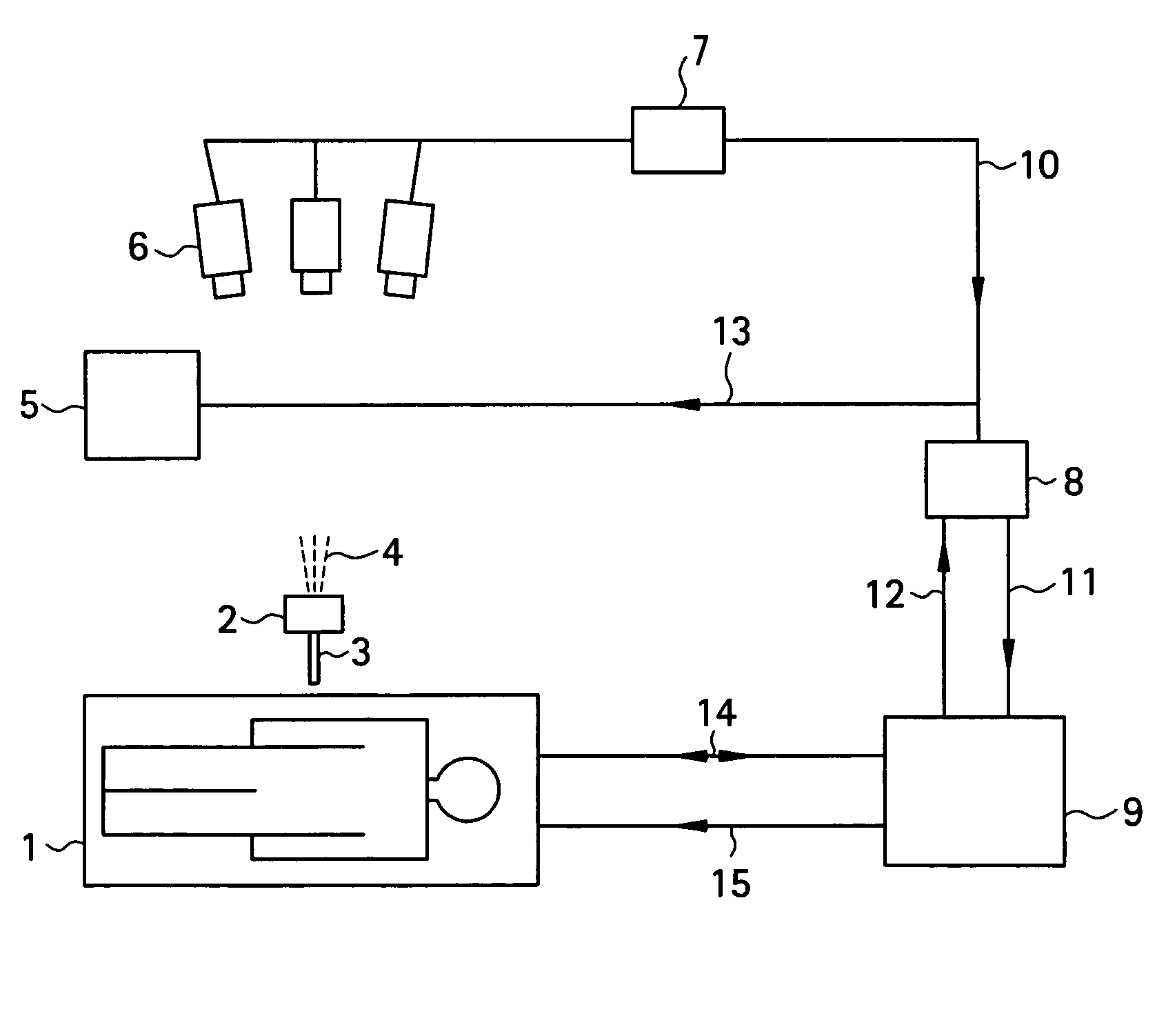
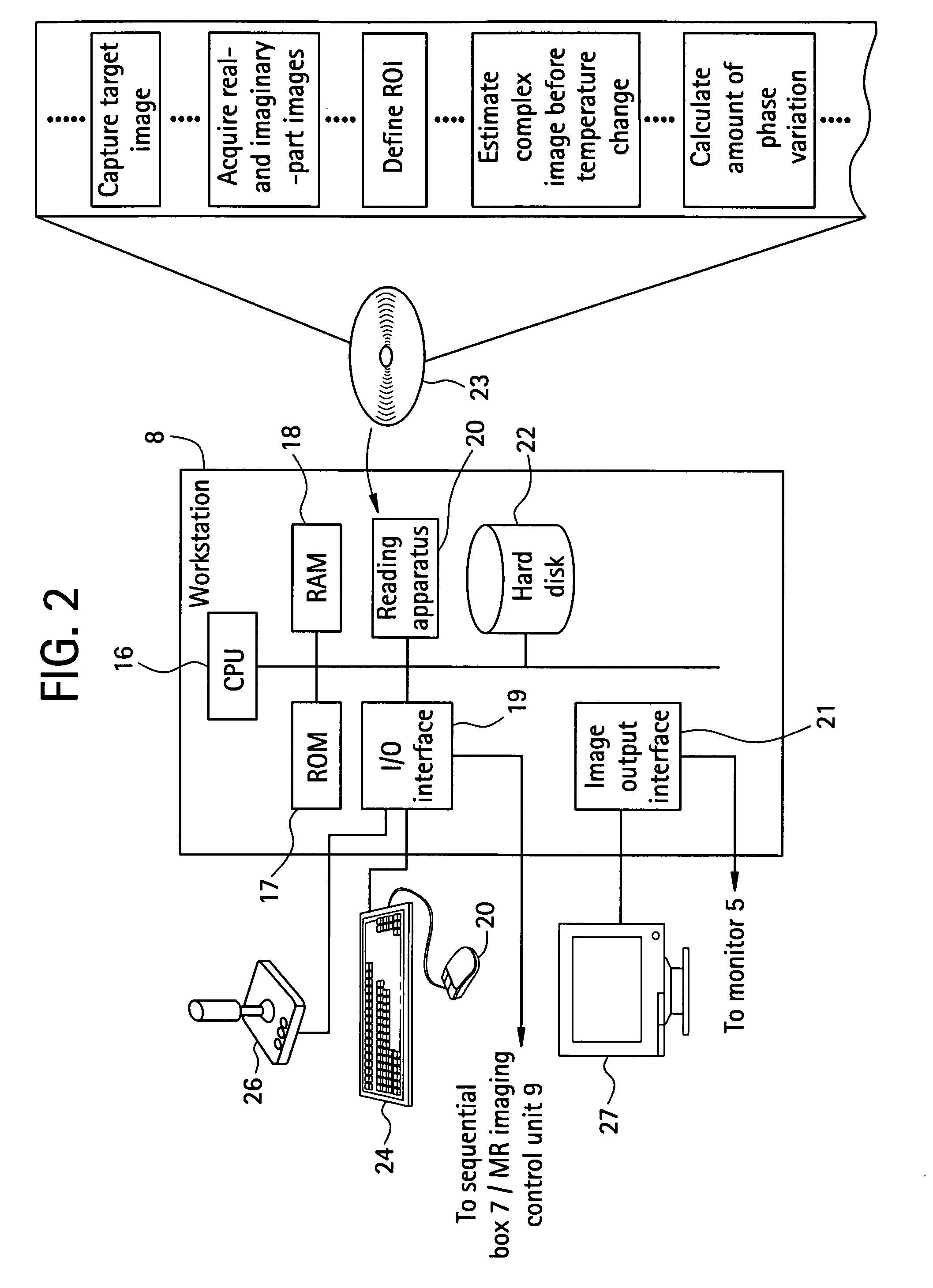
[0037]To begin with, a configuration of a medical MRI apparatus etc. used in the present invention is shown in FIG. 1. The MRI apparatus is attached with an optical positioning apparatus, and infrared radiation 4 emitted by the optical positioning apparatus 2 is imaged by a video camera 6 mounted over the MRI apparatus main portion. The infrared radiation captured by the video camera 6 is converted into a position control signal 10 by a sequential logic box 7 for calculating a position of a probe 3 in a heating needle or the like attached to the optical positioning apparatus 2, and sent to a workstation 8. A personal computer can be employed as the workstation 8. The position control signal 10 is transmitted to an MR imaging control unit 9 via the workstation 8 as an imaging plane adjusting electric signal 11 for controlling an imaging plane. The MRI apparatus main portion 1 and MR imaging control unit 9 communicate RF signals 14 and gradient pulses 15 for capturing a phase distribu...

embodiment 2

[0060]The configuration of a temperature measurement apparatus in accordance with the present embodiment is similar to that of Embodiment 1.

[0061]An amplitude image, a phase image, a real-part image and an imaginary-part image obtained from a complex image captured in one plane including a human liver are shown in FIGS. 5(A)-5(D), respectively.

[0062]In Embodiment 1, a phase image before a temperature change is estimated from a reference phase image after a temperature change, and a phase distribution may contain a portion in which phase transition from −π to π occurs. Thus, if phase transition occurs in the vicinity of a portion at which a temperature change takes place, i.e., in a portion surrounding the region of interest, a phase distribution in a portion surrounding the region of interest becomes rough. Then, an estimation error increases in estimating a phase distribution in the region of interest from a phase distribution in a portion surrounding the region of interest at Step...

embodiment 3

[0067]The configuration of the temperature measurement apparatus in accordance with the present embodiment is similar to that in Embodiments 1 and 2.

[0068]Since in a measured real-part image and a measured imaginary-part image, fat tissue etc. having a high water content is bright and bones etc. having a low water content is dark, smoothness of the signal distribution may sometimes be corrupted by brightness. Now normalizing a measured real-part image and a measured imaginary-part image by dividing them by an amplitude A2 on a pixel-by-pixel basis in the aforementioned Embodiment 2, S2 / A2=cos φ2+j sin φ2 is obtained, in which the right-hand side is expressed only by cos and sin functions. In other words, a real-part image and an imaginary-part image independent of a distribution of brightness are obtained. By using thus-normalized real-part and imaginary-part images, still more accurate estimation of real-part resonance signals and imaginary-part resonance signals in the region of i...


PUM


Abstract

A noninvasive image measuring method of measuring internal organ / tissue temperature using an MRI system. Temperature measurement insusceptible to body motion and spatial variation of magnetic field is realized by utilizing the position and size of a temperature change region as a priori information to determine the phase distribution of the complex magnetic resonance signal of water proton at a given temperature point and by subtracting the phase distribution before the temperature change estimated (self-referred) from the phase distribution in the peripheral region for each pixel of the image, thereby eliminating the subtraction process of image before and after temperature change. The precision of temperature measurement can be enhanced by estimating a complex curved surface formed of the peripheral region in each temperature change region of the real-part and imaginary-part images of the complex magnetic resonance signal, and calculating the phase difference between an actually measured complex signal distribution and the estimated complex signal distribution of the complex signal distribution for each pixel, thereby reducing the estimation error due to phase transition from −π to +π occurring in a phase distribution. Furthermore, temperature can be measured through optimal imaging following up body motion by using an optical positioning system in combination even if the part being measured is shifted.

Description

CROSS REFERENCE TO RELATED APPLICATIONS[0001]This application claims the benefit of PCT / JP2004 / 010160 filed Jul. 9, 2004.BACKGROUND OF THE INVENTION[0002]The present invention relates to a non-invasive measurement method for an internal organ / tissue temperature using a magnetic resonance imaging (MRI) technique, and a method of capturing an optimal MRI image using an optical positioning apparatus during thermotherapy or cryotherapy.SUMMARY OF THE INVENTION[0003]Therapeutic methods against cancers include thermotherapy such as thermoablation, hyperthermia, and the like, in which heating apparatuses employing microwaves, radio frequency (RF) waves, laser or focused ultrasound have been used in need of convenient heating on a localized tumor. Since in such thermotherapy the tumor region to be treated must be heated above a certain temperature while a normal region must be kept below a certain temperature, it is important to accurately measure the temperature of the tumor and normal reg...

Claims


Application Information

Patent Timeline
Patent Type & Authority Patents(United States)
IPC IPC(8): A61B5/05A61B5/00G01R33/28A61B5/055G01R33/48G01R33/54
CPCG01R33/4804A61B5/015A61B5/055
Inventor KURODA, KAGAYAKI
Owner GE MEDICAL SYST GLOBAL TECH CO LLC
Why Eureka
Try Eureka