Visualization, measurement and analysis of vibrating objects

a technology of object and measurement, applied in the field of visualization, measurement and analysis of vibrating objects, can solve the problems of missing reference to an object point, inability to measure the relative motion of two object points, and increasing the scan time according to the density of the measuring point, etc., and achieve the effect of high cost of the camera required

Inactive Publication Date: 2005-12-22
CORRELATED SOLUTIONS
View PDF4 Cites 69 Cited by
  • Summary
  • Abstract
  • Description
  • Claims
  • Application Information

AI Technical Summary

Benefits of technology

[0011] The method can be extended to high-speed stereo speckle photography or 3D digital image correlation where multiple high speed cameras simultaneously record digital images of the object surface at each time, t, and software is used to extract 3D Full-fi...

Problems solved by technology

A disadvantage of the method is that the scan time increases according to the density of the measuring points.
A further disadvantage of any scanning laser vibrometer is the missing reference to an object point for the measurement of relative object motions between points on the object surface.
Therefore, a measurement of the relative motion of two object points is impossible and strain measurements cannot be obtained in the general case.
A further disadvantage are the high costs due to the use of expensive optical components, coherent light sources, vibration isolation compo...

Method used


Image

  • Visualization, measurement and analysis of vibrating objects
  • Visualization, measurement and analysis of vibrating objects
  • Visualization, measurement and analysis of vibrating objects

Examples


Embodiment Construction

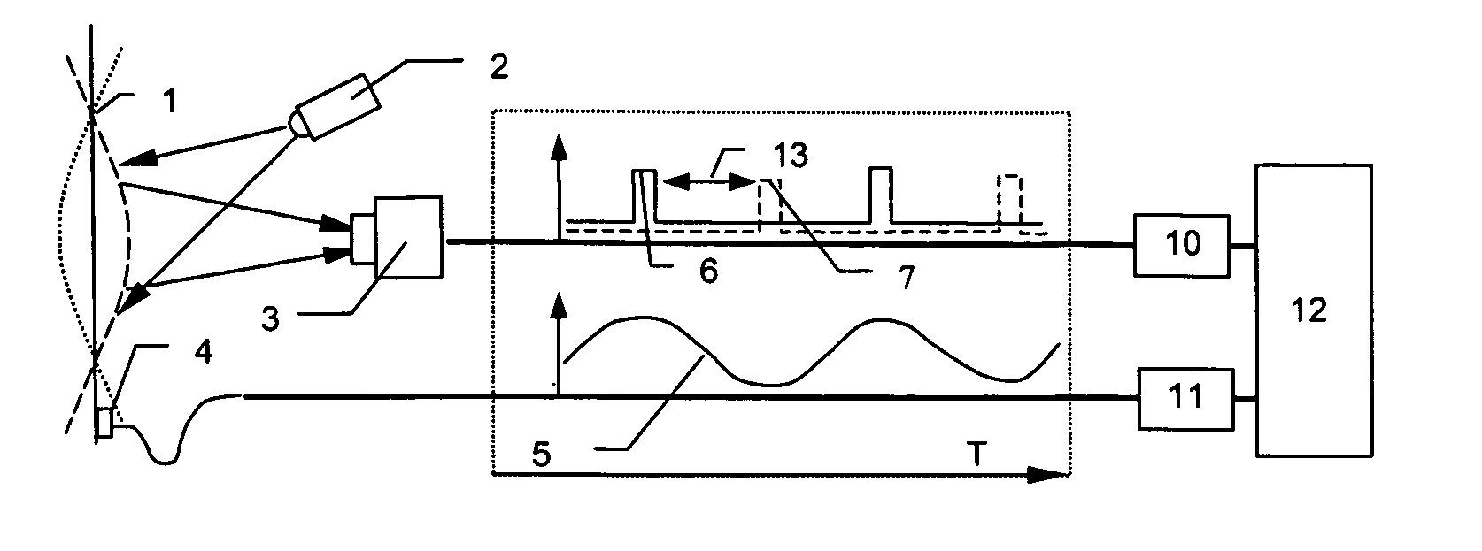
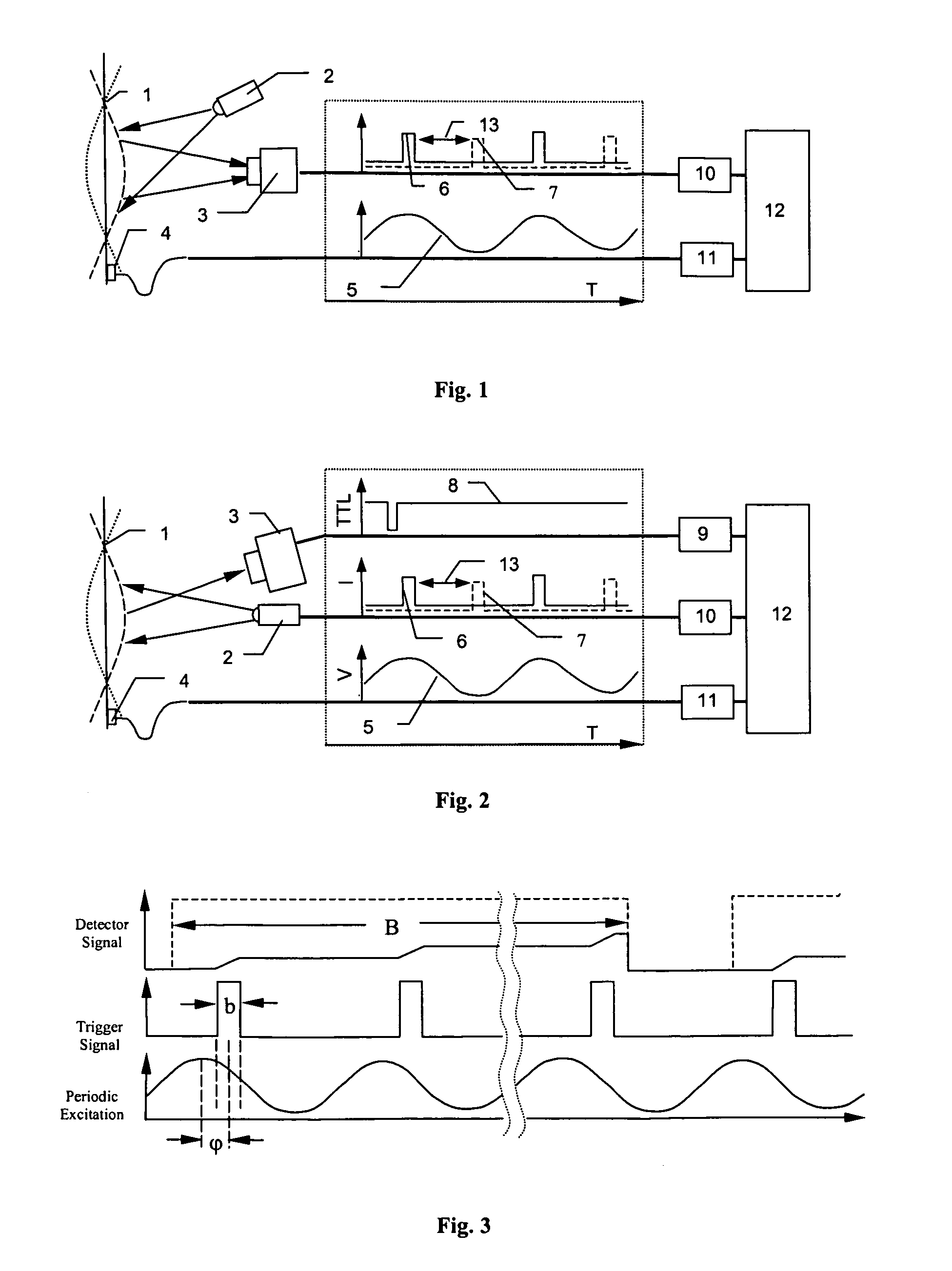
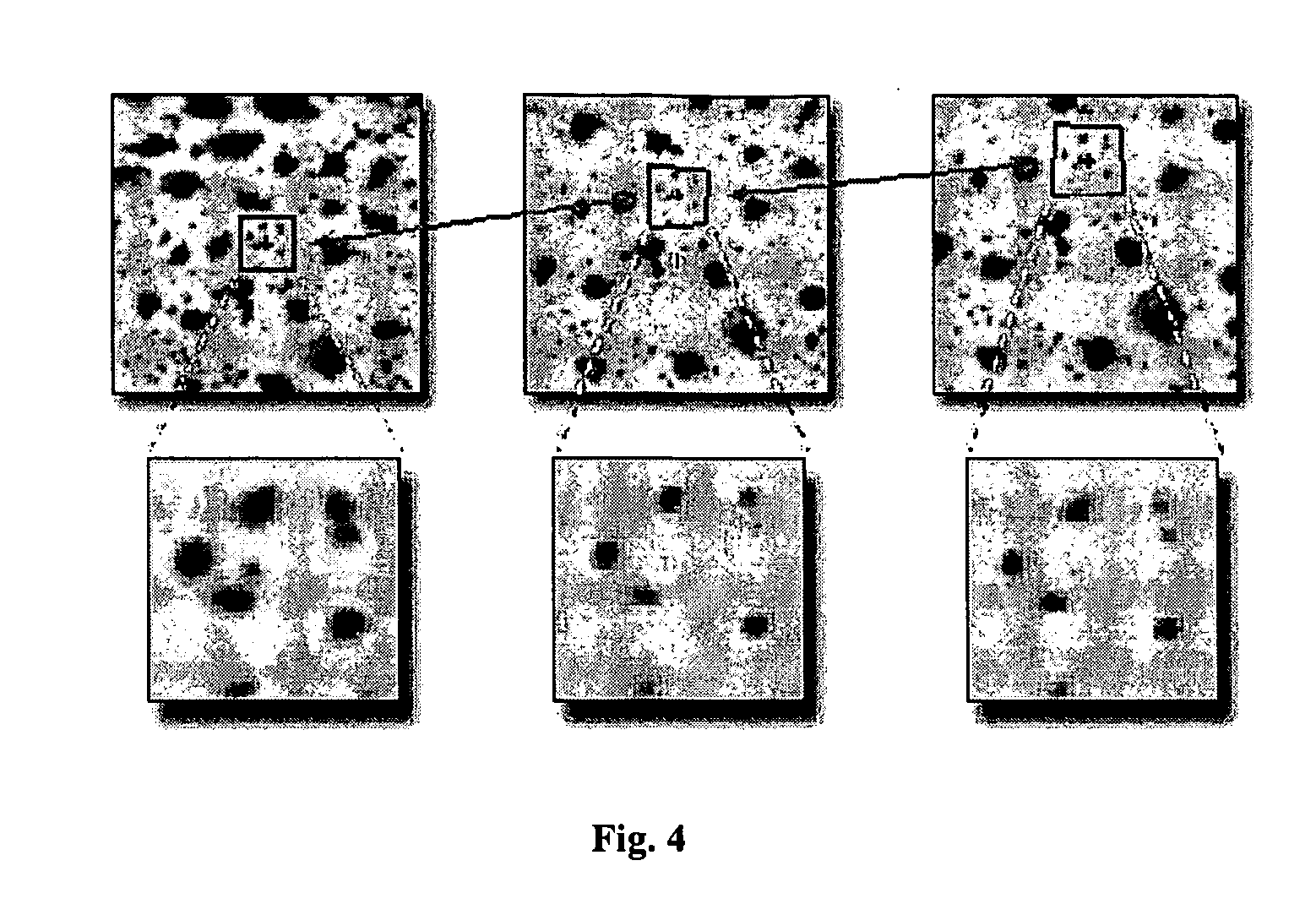
[0016] The presented invention is a procedure to easily and cost-effectively measure and visualize the shape of an object, the motions of an object and the deformations of an object undergoing vibratory oscillation. The method is essentially a combination of stroboscopic image acquisition methods with digital image correlation, particularly 3D digital image correlation, or other image analysis methods, e.g., marker tracking. By means of stroboscopic image recording mechanisms and / or reduced exposure time during image acquisition, sharp images of a vibrating object can be acquired and analysed by digital image correlation or other image processing methods to obtain the object motions. Other derived quantities such vibration amplitudes and phase maps as well as surface strains can then be obtained from the object motions. Procedures and implementations will be referred to as Vibro-Correlation Systems (VIC-S) in the following. In particular, they can be used for vibration measurements ...


PUM


Abstract

A simple, relatively inexpensive, non-contacting, full-field (total visible surface) measurement and visualization methodology is described to measure the object motions and the object stretches and object distortions (deformations) during oscillation of an object. The method is capable of full-field measurement of 1D, 2D and/or 3D object motions and the associated object surface deformations on vibrating objects. The methodology is based on a combination of stroboscopic image ascuisition and/or controlled image exposure time with a synchronization system to acquire the images at appropriate times during periodic oscillation of an object; the periodicity of the applied excitation is used to mitigate the requirement for high speed imaging. Then, image matching procedures, such as 3D digital image correlation, are used with software to extract full-field object motions and surface deformations at each time of interest.

Description

CROSS REFERENCE TO THE RELATED PARTIES [0001] Priority Claim [0002] The present application claims the priority benefit of German patent application number 10 2004 029 552.2, filed on Jun. 18, 2004. BACKGROUND OF THE INVENTION [0003] It is well-known that oscillations are measured by means of sensors such as accelerometers, linear velocity displacement transducers and displacement gauges. These methods measure motions locally at a few discrete locations through contact with the surface. Due to their mass, such sensors can affect the response of the object being measured, which is not the case for optical, non-contacting measurements. [0004] In addition to the effects of mass on the response of an object, such methods typically measure object motions and deformations only along a specific direction and at discrete points. To obtain measurements of motion in all directions at a point, either a combination of several sensors located at the same point or a combination of several experim...

Claims


Application Information

Patent Timeline
IPC IPC(8): G01D5/32G01H9/00G01N21/41
CPCG01B11/167G01H9/002G01B11/2545
Inventor SCHREIER, HUBERT W.MACKEL, PETER
Owner CORRELATED SOLUTIONS
Why Eureka
Try Eureka