
Friction stir bonding method and friction stir bonded substance

A technology of friction stir and joining method, which is applied in the direction of welding/welding/cutting articles, welding equipment, non-electric welding equipment, etc., which can solve the problems such as the reduction of joint strength, achieve the effect of improving the degree of freedom and avoiding the interface exposure

Inactive Publication Date: 2016-02-10
SUZUKI MOTOR CORP
View PDF12 Cites 3 Cited by
  • Summary
  • Abstract
  • Description
  • Claims
  • Application Information

AI Technical Summary

Problems solved by technology

Furthermore, although in principle the shorter the distance between the front end of the tool 103 and the interface 105, the greater the joint strength, but contrary to expectations, the joint strength undesirably decreased.

Method used


Image

  • Friction stir bonding method and friction stir bonded substance
  • Friction stir bonding method and friction stir bonded substance
  • Friction stir bonding method and friction stir bonded substance

Examples


Embodiment 1

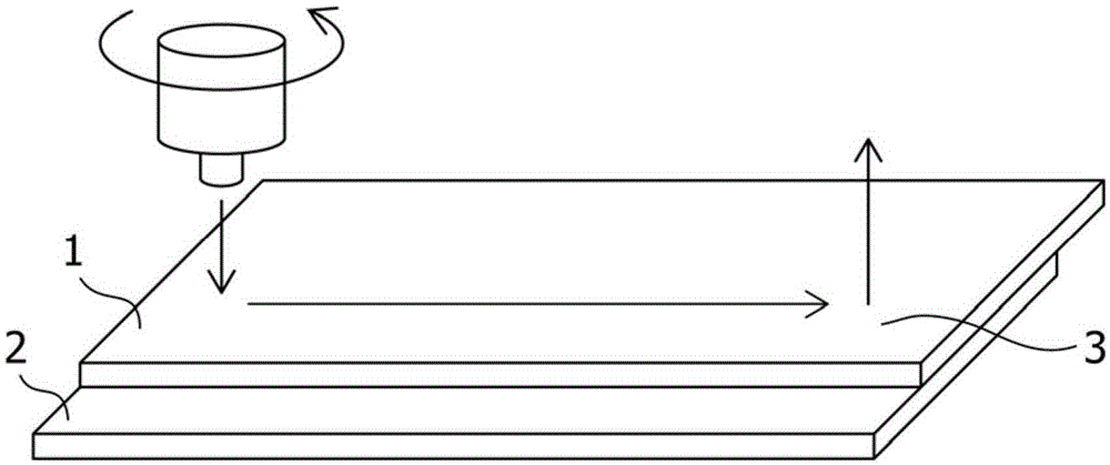
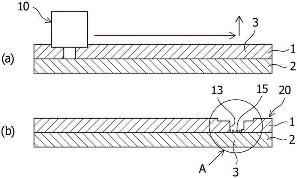
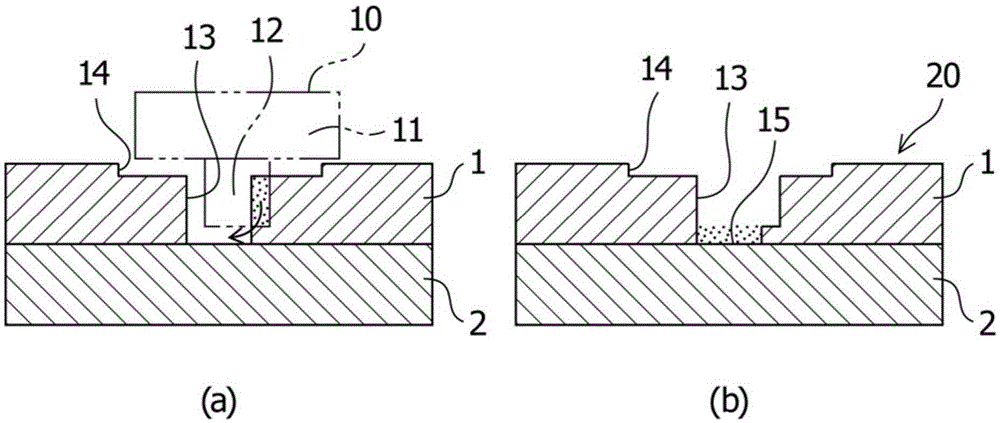
[0054] In this embodiment, the following two types of joints are performed: a joint is performed in the case where two metal members 1 and 2 made of different materials are arranged in such a manner as to overlap each other that the tool 10 is rotated and The tool 10 is brought into contact with the surface of one metal member 1 as an upper plate, and the tool 10 is pulled out from the one metal member 1 while moving in the horizontal direction at the end portion of the friction stir joining; In contrast to the technical method, another joint is performed in which the tool 10 is simply pulled out vertically upwards at the end portion 3 of the friction stir joint.

[0055] Figure 6 The state of the terminal portion 3 of the friction stir welding in this embodiment is shown. In the present embodiment, the tool 10 is pulled out while moving in the horizontal direction at a moving speed of 10 mm / min. As a result, the material in the vicinity of the terminal portion 3 is caused ...

Embodiment 2

[0057] In this example, if Figure 8 and Figure 9 As shown, the joining is performed by pulling out the tool 10 while moving so that the central axis of the tool 10 draws a substantially circular shape at the end portion 3 of the friction stir welding. Specifically, the engagement is performed in such a manner that the diameter d1 of the circle 4 , which represents the circular movement along which the tool 10 is pulled out, varies. Table 1 below shows the experimental results. The joining experiment was carried out in such a manner that the tool hole 13 formed in a metal member 1 (referred to as "D" in Table 1) was made in a state where the diameter d1 of the trajectory circle 4 along which the tool 10 moved was stationary in the horizontal direction with respect to the tool 10. The diameter d2 (=5 mm) of the initial tool hole) is set from 0 mm to 2.5 mm (0 to 50% of the diameter d1 of the tool hole 13 ). As a result, the exposed iron is completely covered. As clearly sh...


PUM


Abstract

Provided are a friction stir bonding method and friction stir bonded material with which, when friction stir bonding metal members made from different metal materials to one another, it is possible to prevent the exposure of a contact part in the joint at which the different metal materials come into contact with one another. In this friction stir bonding method, in which two or more metal members (1, 2) are overlaid upon one another, a tool (10) is pressed against one of the metal members (1), and these two metal members (1, 2) are friction stir bonded together, when the tool (10) is positioned at the end (3) of the friction stir bond, the tool (10) is withdrawn from one of the metal members (1) while being moved in the horizontal direction.

Description

technical field [0001] The present invention relates to a friction stir welding method and a friction stir welded body. Specifically, the present invention relates to a friction stir welding method comprising: overlapping metal members with each other; A tool is pressed against one metal member to join the one metal member to another metal member in a friction stir welding process. Background technique [0002] In the prior art, metal members made of dissimilar metal materials such as iron and aluminum are typically joined to each other by fusion welding, mechanical joining using rivets or other components, or by other joining methods. In mechanical joining using rivets or bolts, rivets or other joining parts are required for joining, which undesirably leads to increased cost, increased weight, and other problems. In view of these circumstances, friction stir welding (FSW: Friction Stir Welding) has been practiced in recent years as a method of joining metal members. Such ...

Claims


Application Information

Patent Timeline
IPC IPC(8): B23K20/12
CPCB23K20/1265B23K20/123B23K20/124B23K2103/18B23K20/12
Inventor 畑山智信
Owner SUZUKI MOTOR CORP
Learn More