
Submersible water impeller for sewage stirring

A technology for submersible flowmakers and sewage, which is applied to mixers with rotating stirring devices, chemical instruments and methods, and dissolution, etc. It can solve the problems of unusable, unchangeable positions, and unsatisfactory use effects of submersible flowmakers. Achieve the effect of simple structure, easy maintenance and improved mixing effect

Inactive Publication Date: 2016-02-17
合肥安奎思成套设备有限公司
View PDF5 Cites 5 Cited by
  • Summary
  • Abstract
  • Description
  • Claims
  • Application Information

AI Technical Summary

Problems solved by technology

[0003] The position of the existing submersible flowmeter cannot be changed according to the actual situation of the sewage, and it cannot be flexibly used according to the actual situation of the sewage
[0004] The effect of the existing submersible thruster is not ideal enough, further improvement is needed

Method used


Image

  • Submersible water impeller for sewage stirring
  • Submersible water impeller for sewage stirring
  • Submersible water impeller for sewage stirring

Examples


Embodiment 1

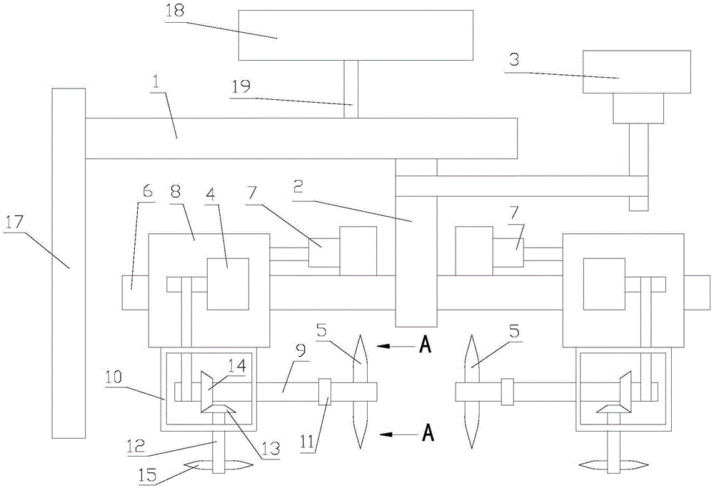
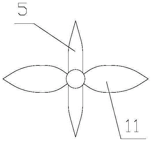
[0022] Embodiment 1: refer to figure 1 , 2 :

[0023] A submersible flowmaker for sewage stirring proposed by the present invention includes a support column 1, a first motor 3, and a support column 2. The support column 2 is rotatably connected to the support column 1, and the support column 2 is provided with N The pushing flow unit includes a second motor 4 and a first blade 5 , the first motor 3 is connected to the pole 2 in transmission, and the second motor 4 is connected to the first blade 5 in transmission.

[0024] The second motor 4 is used to drive the first blade 5 to rotate to stir the sewage.

[0025] Using the first motor 3 to drive the pole 2 to rotate, the position of the push flow unit can be moved, and different areas of the sewage can be stirred. According to the deposition of sewage, the submersible pusher can be flexibly used. In this way, the flexibility is good and the use It has a wide range and is more convenient to use.

[0026] The pushing flow ...

Embodiment 2

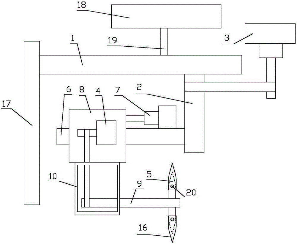
[0048] Example 2, combined with image 3 :

[0049] A submersible pusher for stirring sewage, including a support column 1, a first motor 3, and a support rod 2, one end of the support rod 2 is rotatably connected to the support column 1, and N pieces of flow pushers are arranged on the support rod 2 unit, the pushing flow unit includes a second motor 4 and a first blade 5 , the first motor 3 is in transmission connection with the strut 2 , and the second motor 4 is in transmission connection with the first blade 5 .

[0050] The second motor 4 is used to drive the first blade 5 to rotate to stir the sewage.

[0051] Using the first motor 3 to drive the pole 2 to rotate, the position of the push flow unit can be moved, and different areas of the sewage can be stirred. According to the deposition of sewage, the submersible pusher can be flexibly used. In this way, the flexibility is good and the use It has a wide range and is more convenient to use.

[0052] The pushing flow...


PUM


Abstract

The invention discloses a submersible water impeller for sewage stirring. The submersible water impeller for sewage stirring comprises a support column, a first motor and a support rod; one end of the support rod is rotatably connected with the support column, the support rod is provided with N impelling units, each impelling unit comprises a second motor and first blades, the first motor is in transmission connection with the support rod, and the second motors are in transmission connection with the first blades. According to the submersible water impeller for sewage stirring, an area where sedimentation is serious can be flexibly selected to be stirred according to the sewage sedimentation condition, and therefore the stirring effect is improved; maintenance is convenient, selection can be performed according to the actual condition of sewage, and therefore the flexibility is good; the overall device is simple in structure and convenient to use.

Description

technical field [0001] The invention relates to the technical field of water treatment equipment, in particular to a submersible thruster for stirring sewage. Background technique [0002] The submersible flowmeter is widely used in the aeration tank in the sewage treatment industry. It has the functions of pushing flow and stirring and preventing sludge settlement. It is an indispensable key equipment for sewage treatment. With the increasing investment in sewage treatment and the popularization of sewage treatment all over the world, the market capacity of this equipment is huge. Manufacturers from all over the world are striving to develop high-tech and highly competitive products to lead the world market. [0003] The position of the existing submersible pushers cannot be changed accordingly according to the actual situation of the sewage, and cannot be flexibly used according to the actual situation of the sewage. [0004] The use effect of existing submersible thruste...

Claims


Application Information

Patent Timeline
IPC IPC(8): B01F7/00
Inventor 谢安全黄承大
Owner 合肥安奎思成套设备有限公司
Learn More