
High-pressure spray gun of polyurethane foaming machine

A high-pressure spray gun, foaming machine technology, applied in the direction of spraying devices, single handheld devices, etc., can solve the problems of poor sealing performance, sliding fluid channels, troublesome, time-consuming and labor-intensive problems, and achieve simple and reasonable structure, easy processing and molding, The effect of improving the sealing effect

Active Publication Date: 2016-02-17
蚌埠中正聚氨酯发泡设备有限公司
View PDF8 Cites 6 Cited by
  • Summary
  • Abstract
  • Description
  • Claims
  • Application Information

AI Technical Summary

Problems solved by technology

[0002] At present, the existing high-pressure spray gun of polyurethane foaming machine has the following defects because the spray gun adopts a sliding fluid channel with poor sealing performance and has deficiencies in structural design:
When the spray gun is blocked, the relevant parts must be disassembled before they can be cleaned one by one with a drill bit, which is time-consuming and labor-intensive, and troublesome;
[0005] The spray gun is only used for spraying polyurethane closed-cell insulation materials, and there are fewer types of foam materials that can be sprayed

Method used


Image

  • High-pressure spray gun of polyurethane foaming machine
  • High-pressure spray gun of polyurethane foaming machine

Examples


Embodiment Construction

[0062] The present invention will be described in further detail below in conjunction with the accompanying drawings and embodiments.

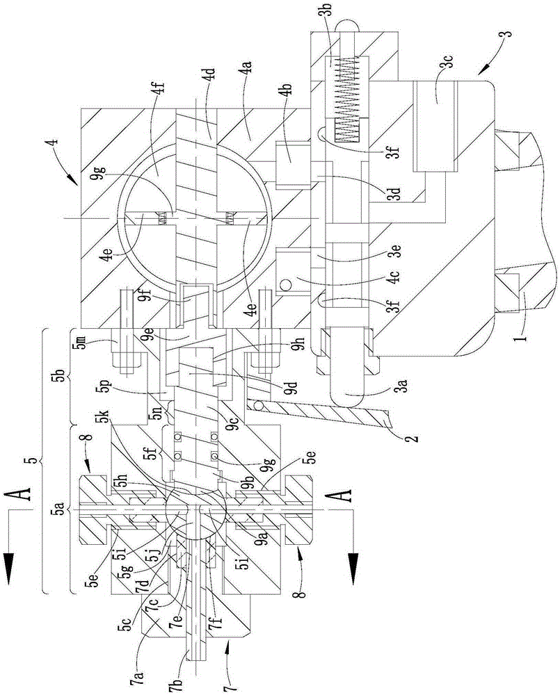
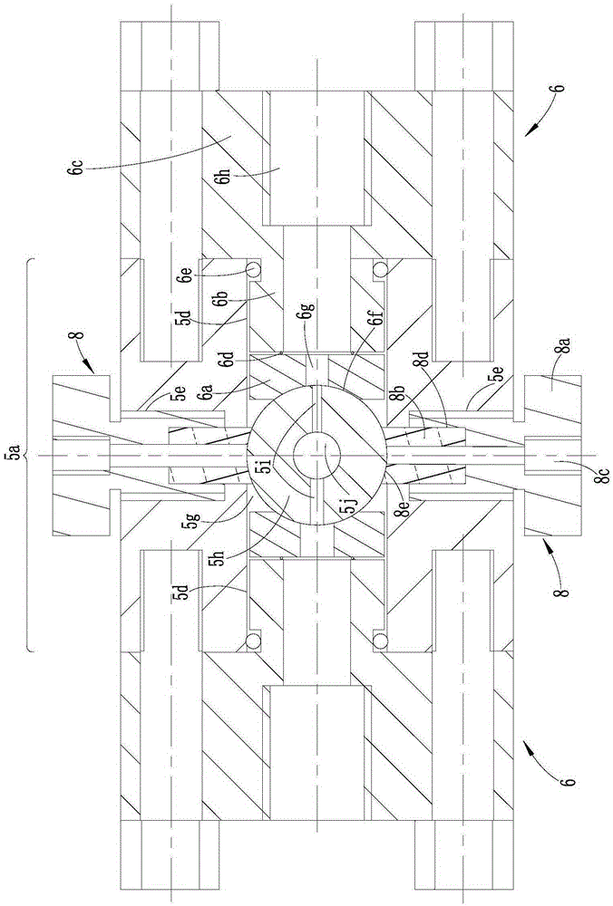
[0063] see figure 1 , figure 2 :

[0064] Polyurethane foaming machine high-pressure spray gun, which includes handle 1, trigger 2, trigger 2 is located on the front side of handle 1, handle 1 is a hollow structure (for the sake of clarity, the handle 1 has been truncated and shortened).

[0065] The upper side of the handle 1 is provided with an air valve 3 and a pneumatic actuator 4 sequentially from bottom to top.

[0066] The air valve 3 adopts a two-position five-way valve, the valve core 3a of the air valve 3 protrudes from the front side of the air valve 3, and the air valve 3 is provided with an air inlet 3c communicating with the valve cavity 3b, a first air outlet 3d, The second air outlet 3e, two exhaust ports 3f.

[0067] The pneumatic actuator 4 adopts a double-acting pneumatic actuator. The pneumatic actuator includes a cyli...


PUM


Abstract

The invention discloses a high-pressure spray gun of a polyurethane foaming machine. The high-pressure spray gun is characterized in that an air valve and a pneumatic actuator are arranged at the upper side of a handle; the upper end of a trigger is articulated with the front side of a cylinder body of the pneumatic actuator, and the middle part of the trigger is in contact with a valve core of the air valve; an output shaft connected to a gear shaft in the cylinder body is arranged at the front side of the cylinder body; the rear side of a combination chamber body is connected to the front side of the cylinder body, and a placement cavity is formed inside the front side of the combination chamber body; a nozzle assembly is arranged at the front end of the combination chamber body; two material injection assemblies and two blowing assemblies are arranged at the front side of the combination chamber body in another two directions being perpendicular to each other; a tee-junction hole comprising two material receiving holes and a material discharging hole is formed in a spherical core block in the placement cavity; the output shaft is placed in the combination chamber body and is connected to the spherical core block; the spherical core block is in close contact with the inner ends of the nozzle assembly, the two material injection assemblies and the two blowing assemblies; during material injection and material clearing, the material injection assemblies and the two blowing assemblies are communicated with the two material receiving holes, and yet the nozzle assembly is always communicated with the material discharging hole. The high-pressure spray gun has a good foaming effect; the frequency of blocking the spray gun is substantially reduced; and the effect of clearing the spray gun is relatively good.

Description

technical field [0001] The invention relates to a high-pressure spray gun of a polyurethane foam machine. Background technique [0002] At present, the existing high-pressure spray gun of polyurethane foaming machine has the following defects because the spray gun adopts a sliding fluid channel with poor sealing performance and has deficiencies in structural design: [0003] When spraying, the pressure of the two raw materials required for polyurethane foaming should not be too high (only 8 MPa), and raw material leakage will occur at the weak position of the corresponding fluid channel, and the mixing uniformity of the two raw materials is poor, and the output The number is low, the foaming effect of the polyurethane foaming mixture is poor, the foaming speed is fast, and the flatness of spraying on the surface of the object is low. In this way, the temperature and viscosity requirements of the above two raw materials are quite high, and the operator's work The operation e...

Claims


Application Information

Patent Timeline
IPC IPC(8): B05B11/02B05B15/00
CPCB05B11/02B05B15/00
Inventor 张绍文张兴为王秀荣
Owner 蚌埠中正聚氨酯发泡设备有限公司
Learn More