Casting blank cutting positioning method and system

A billet and cutting device technology, applied in the field of iron and steel smelting, can solve the problems of low accuracy and high equipment maintenance costs, and achieve the effects of improving accuracy, reducing labor intensity of employees, and reducing industrial accidents

Active Publication Date: 2016-02-17
BEIJING SHOUGANG CO LTD
View PDF6 Cites 7 Cited by
  • Summary
  • Abstract
  • Description
  • Claims
  • Application Information

AI Technical Summary

Problems solved by technology

[0010] The present invention solves the technical problems of low accuracy and high equipment maintenance cost in the cutting and positioning method of the casting slab in the prior art by providing a method and system for cutting and positioning the slab

Method used


Image

  • Casting blank cutting positioning method and system
  • Casting blank cutting positioning method and system

Examples


Embodiment 1

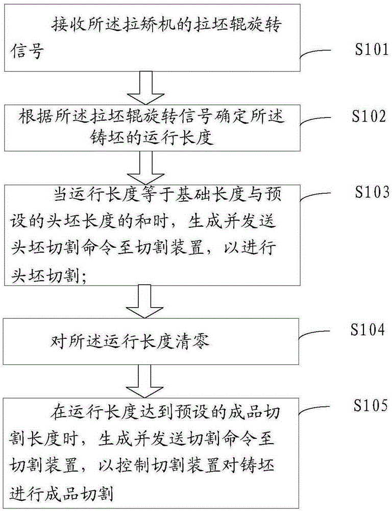
[0048] In this embodiment, a billet cutting and positioning method is provided, the method is applied in electronic equipment, the electronic equipment is connected with the cutting device, and the electronic equipment is connected with the tension leveler, please refer to figure 1 , figure 1 It is a flow chart of the method for cutting and positioning the slab in the embodiment of the present application, such as figure 1 As shown, the method includes:

[0049] Step S101, receiving the drawing roller rotation signal of the drawing and leveling machine;

[0050] Step S102, determining the running length of the cast slab according to the rotation signal of the casting roll;

[0051] Step S103, when the running length is equal to the sum of the base length and the preset length of the first billet, generate and send a first billet cutting command to the cutting device, so as to control the cutting device to cut the first billet on the casting strand ; Wherein, the base length...

Embodiment 2

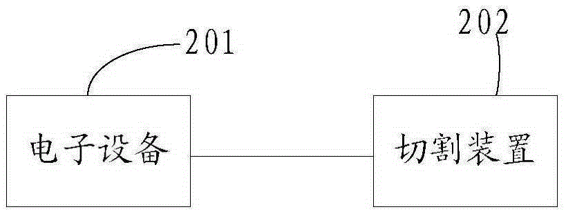
[0067] In this embodiment, a slab cutting positioning system is provided, please refer to figure 2 , figure 2 It is a structural schematic diagram of the cutting and positioning system of the billet in the embodiment of the present application, such as figure 2 As shown, the system includes:

[0068] An electronic device 201 and a cutting device 202 connected to the electronic device 201; wherein the electronic device 201 is connected to a tension leveler;

[0069] Wherein, the electronic device 201 is used for:

[0070] receiving the drawing roller rotation signal of the drawing and leveling machine;

[0071] determining the running length of the cast strand according to the rotation signal of the casting roll;

[0072] When the running length is equal to the sum of the base length and the preset length of the first billet, a first billet cutting command is generated and sent to the cutting device 202, so as to control the cutting device to cut the first billet; , the...


PUM


Abstract

The invention discloses a casting blank cutting positioning method and a system. The method comprises the steps of: receiving a drawing roller rotating signal of a withdrawal and straightening machine; determining an operation length of a casting blank according to the drawing roller rotating signal; generating and sending a head blank cutting command to a cutting device so as to control the cutting device to perform the head blank cutting for the casting blank when the operation length is equal to a sum of a basic length and a preset head blank length, wherein the basic length is a distance from a liquid level of a crystallizer to an original position of a cutting car; zeroing the operation length; and generating and sending a cutting command to the cutting device so as to control the cutting device to perform the finished-product cutting for the casting blank when the operation length reaches a preset finished-product cutting length. The casting blank cutting positioning method and system, provided by the invention, are used for solving the technical problems of low precision and high equipment maintenance cost in a casting blank cutting positioning method of the prior art, and realize the technical effects of improving the cutting positioning precision and reducing the equipment maintenance cost.

Description

technical field [0001] The invention relates to the technical field of iron and steel smelting, in particular to a billet cutting and positioning method and system. Background technique [0002] At present, the billet cutting and sizing system adopts infrared tracking and automatic sizing, that is, the infrared camera is used to track the running length of the high-temperature billet to cut the billet. [0003] However, adopting infrared tracking automatic sizing has the following technical problems: [0004] 1. Light changes in the camera area have a great influence on the accuracy of infrared rays. [0005] 2. Since the lens of the camera must be wiped regularly to keep it clean, it is very easy to cause changes in the camera angle to affect the accuracy of the sizing. [0006] 3. The image signal transmission line of the camera is extremely susceptible to interference from external signals, causing confusion in the sizing system. [0007] 4. Due to the long running tim...

Claims


Application Information

Patent Timeline
Patent Type & Authority Applications(China)
IPC IPC(8): B22D11/126
Inventor 双占博李林杨占岭韩士洋庞博张冬雪
Owner BEIJING SHOUGANG CO LTD
Why Eureka
Try Eureka