
Angle-adjustable inclined valve body clamping mechanism

A technology of clamping mechanism and tilting valve, which is applied in the field of tooling and fixtures, can solve the problems of inconvenient processing of horizontal flange surfaces, inability to clamp and position, and insufficient stability of the structure, so as to facilitate clamping and positioning, ensure processing, and ensure support stability Effect

Active Publication Date: 2016-02-17
CHONGQINGZHICHENG MACHINERY CO LTD
View PDF6 Cites 14 Cited by
  • Summary
  • Abstract
  • Description
  • Claims
  • Application Information

AI Technical Summary

Problems solved by technology

[0003] At present, most valves have horizontal flange surfaces at both ends, which are convenient for processing and positioning; with the demand of the market, there have been valve bodies with one end flange as a horizontal surface and the other end flange as an inclined surface, which cannot be achieved by using conventional tooling. Clamping and positioning, it is not convenient to process the horizontal flange surface, especially for large valve bodies, it is supported by conventional tooling, and the structure is not stable enough

Method used


Image

  • Angle-adjustable inclined valve body clamping mechanism
  • Angle-adjustable inclined valve body clamping mechanism

Examples


Embodiment Construction

[0042] The implementation of the present invention will be illustrated by specific specific examples below, and those skilled in the art can easily understand other advantages and effects of the present invention from the contents disclosed in this specification.

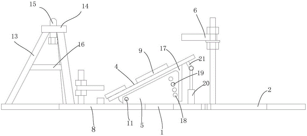
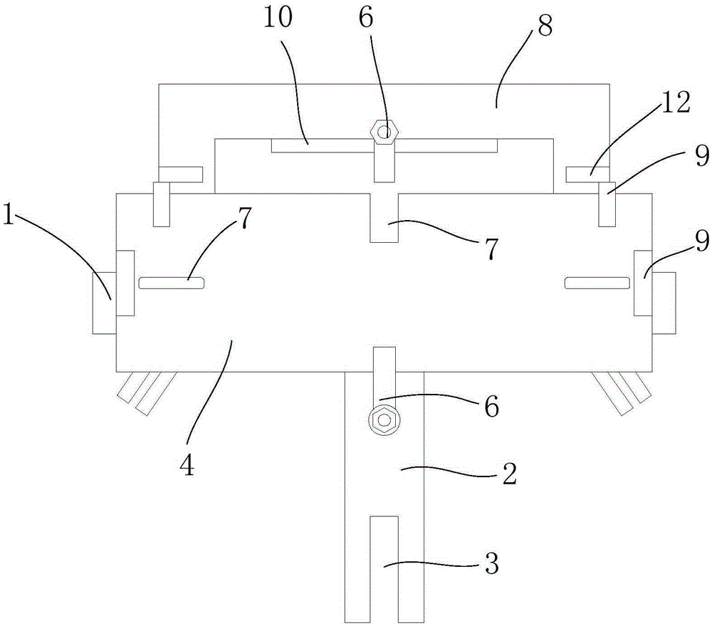
[0043] Such as Figure 1 to Figure 2 As shown, an angle-adjustable inclined valve body clamping mechanism includes a base 1, a support plate 4 and a pressing mechanism 6, and two inclined support blocks 5 are arranged on the base, and the support plate is installed with a low front and a high rear. On the support block 5, the bottom of the support plate is provided with two adjustment plates 17 corresponding to the support block 5, the front portion of the adjustment plate 17 is rotationally connected with the front portion of the support block 5 through the rotating shaft 11, and the rear portion of the adjustment plate 17 is provided with Locking holes, the back of the support block 5 is provided with a plurality ...


PUM


Abstract

The invention provides an angle-adjustable inclined valve body clamping mechanism which comprises a base, a supporting plate and a compression mechanism. The base is provided with two inclined supporting blocks. The supporting plate is installed on the supporting blocks in an inclined mode with the lower front portion and the higher rear portion. The bottom of the supporting plate is provided with two adjusting plates corresponding to the supporting blocks. The front portions of the adjusting plates are rotationally connected with the front portions of the supporting blocks through rotating shafts. The rear portions of the adjusting plates are provided with locking holes. The rear portions of the supporting blocks are provided with a plurality of height adjusting holes. The adjusting plates and the supporting blocks are fixed through positioning pin shafts penetrating in the height adjusting holes and the locking holes. A supporting mechanism used for supporting the upper end of a valve body is arranged in front of the base. When the angle-adjustable inclined valve body clamping mechanism is in use, an inclined flange face of the inclined valve is supported on the supporting plate, primary positioning is achieved through a bolt and a positioning hole, and then compression is carried out through a compressing mechanism. The angle of the supporting plate can be adjusted when the adjusting plates rotate around the rotating shafts, and therefore valve bodies of different inclined angles can be clamped.

Description

technical field [0001] The invention belongs to the technical field of fixtures, in particular to an angle-adjustable tilting valve body clamping mechanism. Background technique [0002] A valve is a device used to control the direction, pressure, and flow of a fluid in a fluid system. It is a device that allows the medium (liquid, gas, powder) in the piping and equipment to flow or stop and can control its flow. The processing accuracy of the valve directly affects the sealing performance of the entire pipeline. [0003] At present, most valves have horizontal flange surfaces at both ends, which are convenient for processing and positioning; with the demand of the market, there have been valve bodies with one end flange as a horizontal surface and the other end flange as an inclined surface, which cannot be achieved by using conventional tooling. Clamping and positioning are not convenient for processing horizontal flange surfaces, especially for large valve bodies, which ...

Claims


Application Information

Patent Timeline
Patent Type & Authority Applications(China)
IPC IPC(8): B25B11/00B23Q3/06
CPCB23Q3/062B25B11/00
Inventor 孙仁坤
Owner CHONGQINGZHICHENG MACHINERY CO LTD
Learn More