Clamping tool for pipeline experiment

A technology for clamping tooling and pipelines, applied in auxiliary devices, manufacturing tools, metal processing equipment, etc., can solve the problems that the bellows cannot be in a free state, damage the installation size of parts, and angle differences, etc.

Pending Publication Date: 2017-09-22
LIUZHOU WULING MOTORS +1
View PDF0 Cites 4 Cited by
  • Summary
  • Abstract
  • Description
  • Claims
  • Application Information

AI Technical Summary

Problems solved by technology

[0003] Welding the flanges at the two ports of the bellows is not only cumbersome to operate, but also the angle difference between the welding flanges makes the bellows unable to be in a free state after clamping, thus affecting the experimental results
Moreover, the bellows after the experiment have destroyed the original installation size of the parts due to welding, which limits the flexibility of the experiment, and it is impossible to carry out the vehicle loading test on the parts that have been tested for (dynamic and static) stiffness.

Method used


Image

  • Clamping tool for pipeline experiment
  • Clamping tool for pipeline experiment
  • Clamping tool for pipeline experiment

Examples


Embodiment Construction

[0027] The core of the present invention is to provide a pipeline experiment clamping tool, which can effectively limit the pipeline without welding, so as to avoid various problems caused by welding.

[0028] Hereinafter, an embodiment will be described with reference to the drawings. In addition, the examples shown below do not limit the content of the invention described in the claims in any way. In addition, all the contents of the configurations shown in the following embodiments are not limited to be essential to the solutions of the invention described in the claims.

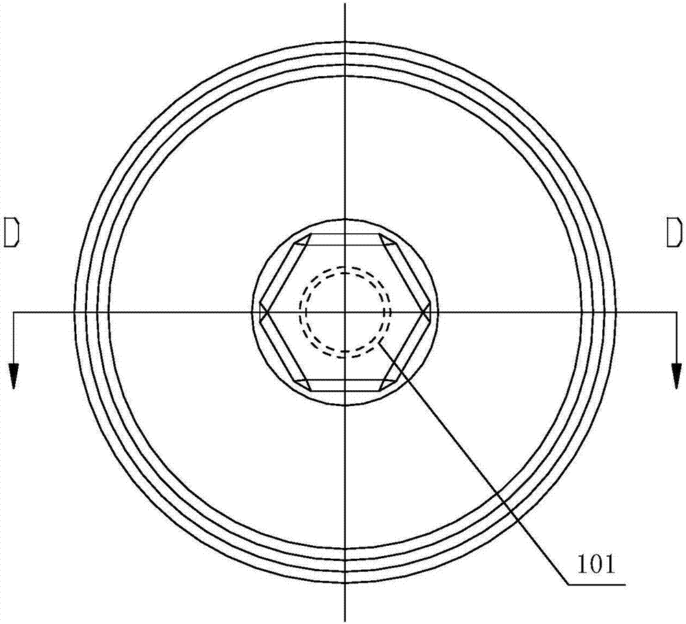
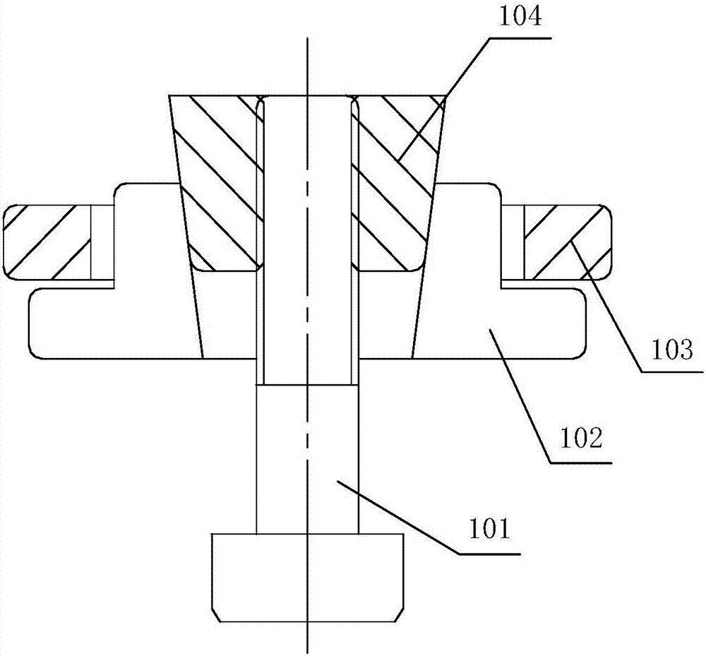
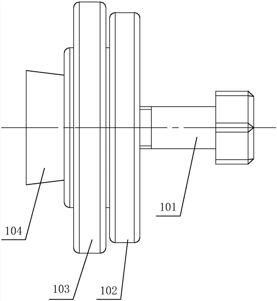
[0029] see Figure 1-Figure 3 , figure 1 The front view of the pipeline experiment clamping tool provided by the embodiment of the present invention; figure 2 for figure 1 Sectional view along line D-D; image 3 It is a side view of the clamping tool for pipeline experiment provided by the embodiment of the present invention.

[0030] The embodiment of the present invention discloses a clamping too...


PUM

PropertyMeasurementUnit
Widthaaaaaaaaaa

Abstract

The embodiment of the invention discloses a clamping tool for pipeline experiment. The clamping tool comprises an expanding clamping jaw, a limiting ring which sleeves outside the expanding clamping jaw, an expanding pin matched with an expanding hole, a clamping plate for allowing a clamp to pass through, and a screw matched with a threaded hole, wherein the expanding hole is formed inside the expanding clamping jaw; space for allowing a pipeline end opening to insert is formed between the expanding clamping jaw and the limiting ring; the expanding pin is provided with the threaded hole; when matching depth of the expanding pin and the expanding hole is increased, the expanding clamping jaw expands in the radial direction; a positioning plate is arranged at one end of the screw; and space for clamping the clamping plate is formed between the positioning part and the expanding clamping jaw. According to the clamping tool disclosed by the invention, a flange plate does not need to weld in the pipeline end opening, and clamping for pipelines also can be realized, so that various problems caused by welding are avoided.

Description

technical field [0001] The invention relates to the technical field of clamping fixtures, more specifically, to a clamping fixture for pipeline experiments. Background technique [0002] In order to verify whether the corrugated pipe meets the requirements, it is necessary to conduct a test bench test on the corrugated pipe, and then carry out the loading test. In the prior art, the clamping method adopted in the experiment of the laboratory bench is to weld a flange plate at the ports at both ends of the bellows, and connect the flange plate to the experimental tooling. [0003] Welding the flanges at the two ports of the bellows is not only cumbersome to operate, but also the angle difference of the welding flanges makes the bellows unable to be in a free state after clamping, thus affecting the experimental results. Moreover, the bellows after the experiment have destroyed the original installation size of the parts due to welding, which limits the flexibility of the exp...

Claims


Application Information

Patent Timeline
IPC IPC(8): B23K37/053
CPCB23K37/0536
Inventor 马果傅爱军杨迪新李飞翔曾宪民
Owner LIUZHOU WULING MOTORS
Why Eureka
Try Eureka