Three-segment type mobile phone shell U cover positioning device

A technology of mobile phone casing and positioning device, applied in coating and other directions, can solve problems such as low production efficiency, poor quality controllability, and high labor intensity of operators

Active Publication Date: 2016-02-17
GUANGDONG TOPSTAR TECH
View PDF4 Cites 0 Cited by
  • Summary
  • Abstract
  • Description
  • Claims
  • Application Information

AI Technical Summary

Problems solved by technology

When manufacturing this kind of mobile phone shell with special structure, the current common practice is to rely on manual operation of workers to place the main shell and the U covers at both ends at predetermined positions in the cavity of the injection mold, and then carry out the process on the injection molding machine. Injection molding to complete the manufac

Method used


Image

  • Three-segment type mobile phone shell U cover positioning device
  • Three-segment type mobile phone shell U cover positioning device
  • Three-segment type mobile phone shell U cover positioning device

Examples


Embodiment 1

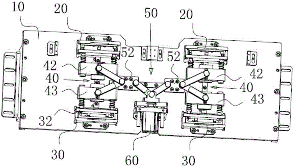
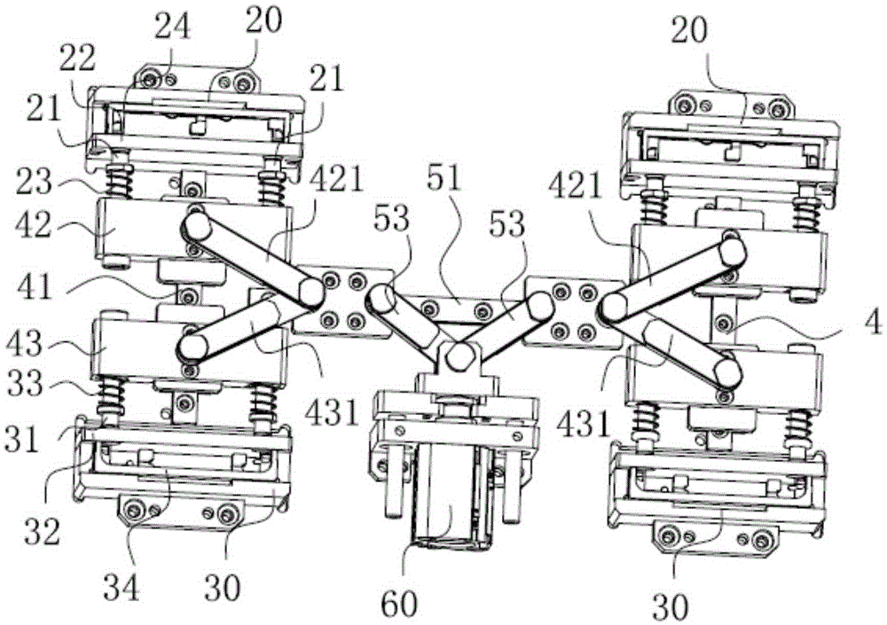
[0033] Such as figure 1 and figure 2 As shown, the three-section mobile phone casing U cover positioning device described in the application, the three-section mobile phone casing U cover positioning device includes a base 10, and a U-shaped upper positioning frame 20 and a U-shaped upper positioning frame affixed to the base 10. The lower positioning box 30. The upper positioning frame 20 and the lower positioning frame 30 are all set to U-shaped, which is convenient for the positioning of the U-shaped upper U cover and the lower U cover, not only positioning the distance between the upper and lower U cover, but also positioning the U cover. correct. The upper positioning frame 20 and the lower positioning frame 30 are arranged oppositely, and a push rod device is arranged between the upper positioning frame 20 and the lower positioning frame 30. The push rod device includes an upper push rod 21, a lower push rod 31, and drives the upper push rod 21 and the lower push rod....

Embodiment 2

[0045] The structure of this embodiment is basically the same as that of Embodiment 1, and the similarities will not be repeated here. The difference between it and Embodiment 1 mainly lies in:

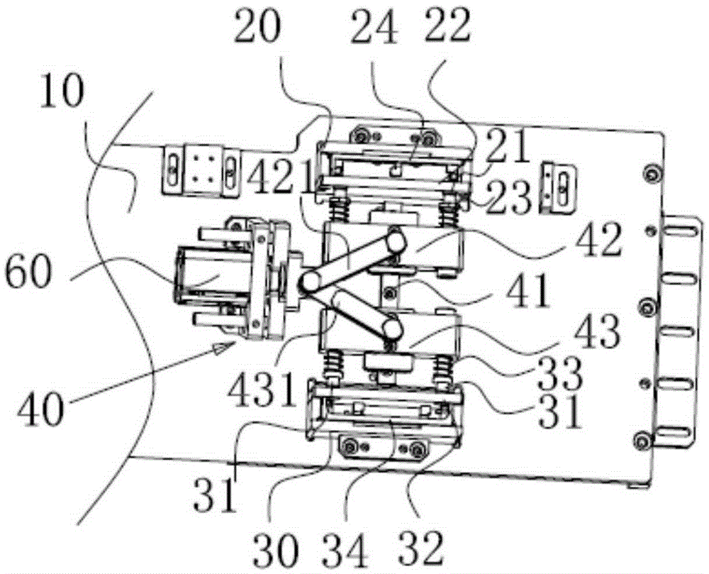
[0046] Such as image 3 As shown, the driving device includes a longitudinal driving device 40 and a driver 60, and the longitudinal driving device 40 includes a longitudinal linear guide rail 41, a longitudinal upper slider 42, a longitudinal lower slider 43, and a longitudinal upper driving arm 421, a longitudinal lower driving arm 431, an upper top One end of the rod 21 is fixedly connected to the vertical upper slider 42, and one end of the lower ejector rod 31 is fixedly connected to the vertical lower slider 43. The direction of the longitudinal linear guide 41 is along the direction from the upper positioning frame 20 to the lower positioning frame 30. The slide block 42 and the longitudinal lower slide 43 can slide on the longitudinal linear guide rail 41, one end of the drive...


PUM


Abstract

The invention belongs to the technical field of mobile phone shell manufacturing and relates to a three-segment type mobile phone shell U cover positioning device. The three-segment type mobile phone shell U cover positioning device comprises a base, an upper positioning frame and a lower positioning frame; the upper positioning frame and the lower positioning frame are fixedly connected to the base and are oppositely arranged; an ejecting rod device is arranged between the upper positioning frame and the lower positioning frame and comprises an upper ejecting rod, a lower ejecting rod and a driving device driving the upper ejecting rod and the lower ejecting rod to move; the upper ejecting rod and the upper positioning frame are matched to position an upper U cover; the lower ejecting rod and the lower positioning frame are matched to positioning a lower U cover; the distance between the upper positioning frame and the lower positioning frame is adjusted and determined in advance according to the size requirement of a mobile phone shell; the upper U cover is placed in the upper positioning frame through a feeding device or is manually placed in the upper positioning frame; the lower U cover is placed in the lower positioning frame; the driving device synchronously drives the upper ejecting rod and the lower ejecting rod to move; the upper U cover is tightly ejected in the upper positioning frame by the upper ejecting rod; the lower U cover is tightly ejected in the lower positioning frame by the lower ejecting rod; and the purpose of fixing the position of the upper U cover, the position of the lower U cover and the relative position of the upper U cover and the lower U cover is achieved.

Description

technical field [0001] The application belongs to the technical field of mobile phone shell manufacturing, and in particular relates to a three-stage mobile phone shell U cover positioning device. Background technique [0002] Portable computers and electronic devices, such as handheld computers, media players, and cell phones, are becoming more sophisticated, powerful, and user-friendly. Manufacturing these devices requires miniaturization and ultra-thinning while still maintaining or increasing the functionality, speed of operation, and aesthetics of these devices. However, this trend toward smaller, lighter, and more powerful portable computers presents ongoing design challenges in the actual formation of some of the components of these devices. One design challenge associated with such electronic devices and their components is forming an external enclosure or housing for housing the various internal device components therein. While many designs and technologies for ho...

Claims


Application Information

Patent Timeline
IPC IPC(8): B29C45/14B29C45/17B29C33/12
CPCB29C45/14065
Inventor 张安平
Owner GUANGDONG TOPSTAR TECH
Why Eureka
Try Eureka