
A horizontal overflow forming device for ultra-thin flat glass

A technology of ultra-thin flat glass and forming device, which is applied in glass forming, glass forming, glass manufacturing equipment, etc. It can solve the problems of reducing production cost, difficulty in debugging, and long cycle, so as to reduce production cost and shorten debugging The effect of cycle and simple structure

Active Publication Date: 2017-08-04
(CNBM) BENGBU DESIGN & RES INST FOR GLASS IND CO LTD
View PDF4 Cites 0 Cited by
  • Summary
  • Abstract
  • Description
  • Claims
  • Application Information

AI Technical Summary

Problems solved by technology

The existing forming device includes a base made of refractory material, an overflow groove is provided at the top of the base, overflow slopes are also provided on both sides of the overflow groove at the top of the base, and a glass liquid injection port is provided at one end of the base. When the molten glass flows into the overflow tank from the molten glass inlet, the molten glass flows from one end of the overflow tank to the other end of the overflow tank. In order to ensure that the overflow volume of each part of the forming machine is consistent, the thickness of the plate glass formed by the overflow is consistent. , in addition to strictly controlling the structural size of the forming device, it is also necessary to control the inclination angle of the overflow surface, the viscosity of the glass liquid, the temperature of the glass liquid, the molding speed, the injection speed of the glass liquid, the width of the glass plate, the thickness of the glass plate, the composition of the raw materials, and the environment. Repeated debugging of parameters such as temperature is difficult and the cycle is long, which is not conducive to reducing production costs

Method used


Image

  • A horizontal overflow forming device for ultra-thin flat glass
  • A horizontal overflow forming device for ultra-thin flat glass

Examples


Embodiment Construction

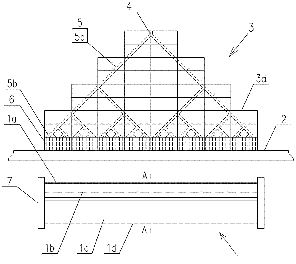
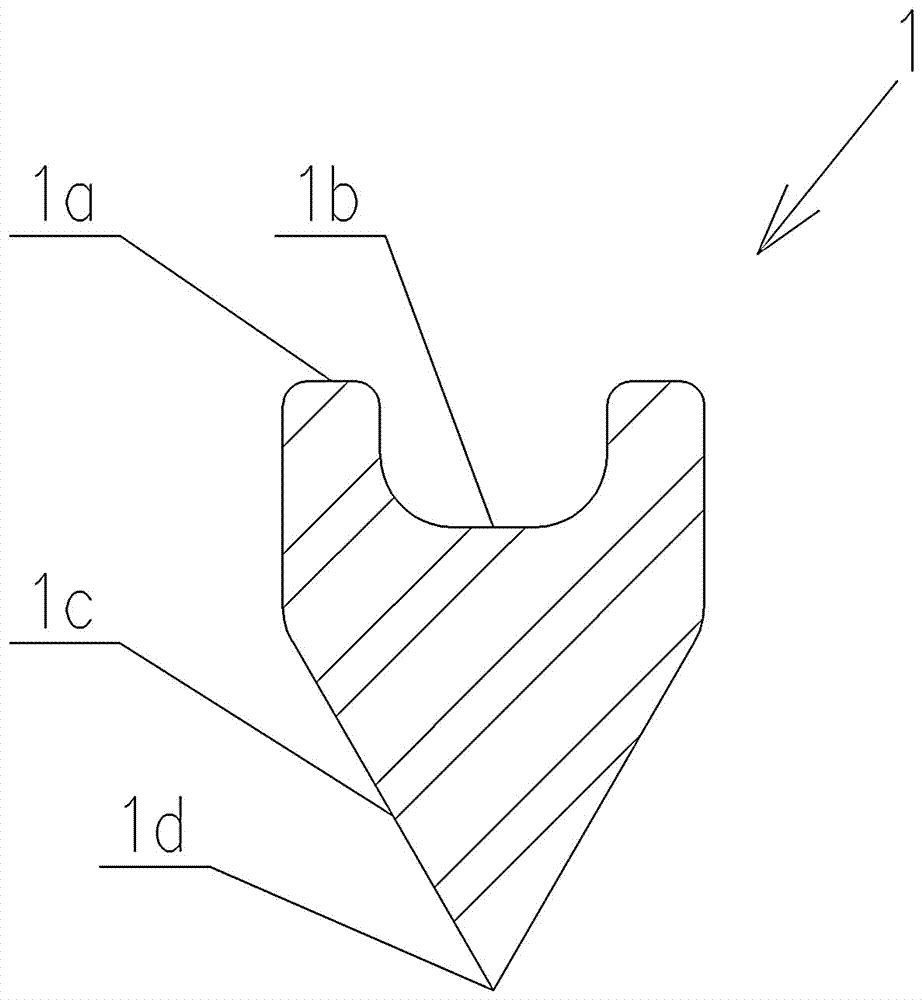
[0014] Such as figure 1 and figure 2 As shown, a horizontal overflow forming device for ultra-thin flat glass provided by the present invention includes a base body 1, two ends of the base body 1 are respectively provided with retaining walls 7, and the lower side of the base body 1 is provided with two symmetrically arranged The diversion slope 1c, the lower ends of the corresponding diversion slopes 1c are connected to each other, and form a forming edge 1d, the top of the seat body 1 is provided with an overflow groove 1b, and the two sides of the overflow groove 1b at the top of the seat body 1 are also provided with an overflow slope 1a , the bottom surface of the overflow tank 1b and the overflow surface 1a are parallel to each other, a support 2 is provided above the seat body 1, and a flow guide device 3 is provided on the support 2. The flow guide device 3 is composed of a group of refractory bricks 3a, and the flow guide The upper side of the device is provided wit...


PUM


Abstract

The invention relates to a horizontal overflow forming device for ultra-thin flat glass, which comprises a base body (1) and a retaining wall (7). The lower side of the base body (1) is provided with two diversion slopes (1c) arranged symmetrically to each other. The lower ends of the two diversion slopes (1c) are connected to each other and form a forming edge (1d). An overflow groove (1b) is provided on the top of the seat body, and overflow slopes (1a) are provided on both sides of the overflow groove. It is characterized in that A diversion device (3) is provided directly above the seat body, a glass liquid injection port (4) is arranged on the upper side of the flow diversion device, and a row of glass liquid outlets (6) connected to the glass liquid injection port is uniformly arranged on the lower side, The axis of each molten glass outlet is perpendicular to the central axis of the overflow tank (1b). The invention has the advantages of simple structure and high stability, and changes the injection mode of the glass liquid, and evenly distributes the glass liquid through a group of inverted V-shaped flow channels connected step by step, so that the glass liquid level in the overflow tank The height is equal everywhere.

Description

technical field [0001] The invention relates to production equipment for manufacturing ultra-thin flat glass, in particular to a horizontal overflow former for producing ultra-thin flat glass. Background technique [0002] At present, in the field of flat glass, especially ultra-thin flat glass manufacturing, the main forming processes include overflow down-draw method, slot down-draw method, float method, etc. In the overflow down-draw method and slot-hole down-draw forming process, a former is used to draw high-temperature molten glass into a flat glass plate. The existing forming device includes a base made of refractory material, an overflow groove is provided at the top of the base, overflow slopes are also provided on both sides of the overflow groove at the top of the base, and a glass liquid injection port is provided at one end of the base. When the molten glass flows into the overflow tank from the molten glass inlet, the molten glass flows from one end of the ove...

Claims


Application Information

Patent Timeline
Patent Type & Authority Patents(China)
IPC IPC(8): C03B17/06
Inventor 彭寿方强张治民
Owner (CNBM) BENGBU DESIGN & RES INST FOR GLASS IND CO LTD
Learn More