
Upper and lower airfoil deformation superposition method

A superposition method and airfoil technology, applied in special data processing applications, instruments, electrical digital data processing, etc., can solve problems such as limitations and increase the difficulty of airfoil mesh distribution, and achieve the effect of improving the application range

Inactive Publication Date: 2016-02-17
NANJING UNIV OF AERONAUTICS & ASTRONAUTICS
View PDF1 Cites 6 Cited by
  • Summary
  • Abstract
  • Description
  • Claims
  • Application Information

AI Technical Summary

Problems solved by technology

According to the flexibility method, the structural deformation at the cell center of the airfoil aerodynamic grid is equal to the force vector composed of the flexibility matrix in the aerodynamic grid system multiplied by the corresponding aerodynamic force of the upper and lower airfoil units, so the aerodynamic mesh of the upper and lower airfoils is required Grid overlap on the projection plane is difficult to achieve for asymmetric airfoils in practical applications, which increases the difficulty of airfoil grid distribution and limits the application of static aeroelastic CFD / CSD coupling calculations

Method used


Image

  • Upper and lower airfoil deformation superposition method
  • Upper and lower airfoil deformation superposition method
  • Upper and lower airfoil deformation superposition method

Examples


Embodiment Construction

[0031] The specific embodiments of the present invention will be further described in detail below in conjunction with the accompanying drawings.

[0032] Exemplary embodiments of the present disclosure will be described in more detail below with reference to the accompanying drawings. Although exemplary embodiments of the present disclosure are shown in the drawings, it should be understood that the present disclosure may be embodied in various forms and should not be limited by the embodiments set forth herein. Other embodiments may include structural, logical, electrical , process, and other changes. The examples merely represent possible variations. Rather, these embodiments are provided for more thorough understanding of the present disclosure and to fully convey the scope of the present disclosure to those skilled in the art. These embodiments of the present invention may be referred to herein individually or collectively by the term "invention", which is for convenien...


PUM


Abstract

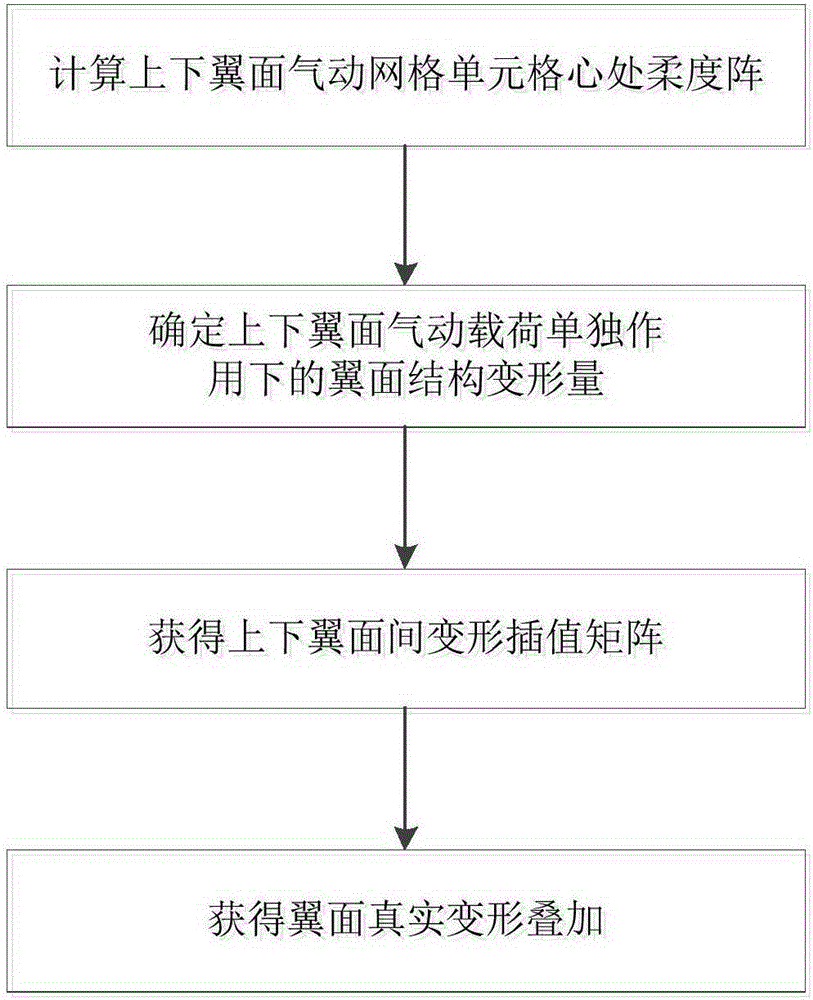
The invention provides an upper and lower airfoil deformation superposition method. The method comprises the following steps: determining and obtaining flexibility matrixes in the centers of aerodynamic grid units of upper and lower airfoils; with a flexibility method, decomposing airfoil structure deformation into superposition of deformations generated under the single action of aerodynamic loads of the upper airfoil and the lower airfoil, and obtaining airfoil structure deformation amounts under the single action of the aerodynamic loads of the upper airfoil and the lower airfoil; according to initial static grid coordinates of the airfoils, obtaining deformation interpolation matrixes between the upper airfoil and the lower airfoil with a surface spline method, wherein the deformation interpolation matrixes between the upper airfoil and the lower airfoil include a deformation interpolation matrix [TUL] from the grid center of the upper airfoil to the grid center of the lower airfoil, an interpolation matrix [TLL] from the grid center of the lower airfoil to grid points of the lower airfoil, and an interpolation matrix [TLU] from the grid center of the lower airfoil to grid points of the upper airfoil; and according to the airfoil structure deformation amounts under the single action of the aerodynamic loads of the upper airfoil and the lower airfoil, and the deformation interpolation matrixes of the upper airfoil and the lower airfoil, determining upper and lower airfoil deformation superposition. According to the method, flexibility method based static aeroelastic CFD / CSD coupling calculation is suitable for any airfoil grid distribution situation.

Description

technical field [0001] The invention relates to a method in the field of computational fluid dynamics, in particular to a method for superimposing deformations of upper and lower airfoils. Background technique [0002] Aeroelasticity is an interdisciplinary subject that studies the interaction among aerodynamic force, elastic force and inertial force. In the early 1990s, domestic and foreign researchers began to devote themselves to the research of aeroelastic CFD / CSD coupled iterative calculation method based on Euler / N-S equation. At present, CFD / CSD coupling calculation has been widely used in engineering practice, but there are still some technical difficulties and technical details to be resolved. The static aeroelastic problem ignores the influence of inertial force, and its CFD / CSD coupling calculation adopts the method of alternating iterative calculation of steady aerodynamic force and structural deformation until convergence, while the static deformation of the ai...

Claims


Application Information

Patent Timeline
Patent Type & Authority Applications(China)
IPC IPC(8): G06F17/50
CPCG06F30/367Y02T90/00
Inventor 郭同庆陈皓陆志良
Owner NANJING UNIV OF AERONAUTICS & ASTRONAUTICS
Learn More