Thermal imaging image processing method and device

An image processing and thermal imaging technology, applied in the field of image processing, can solve problems such as unrecognized targets and lack of details in thermal imaging images.

Active Publication Date: 2016-02-17
ZHEJIANG DAHUA TECH CO LTD
View PDF4 Cites 12 Cited by
  • Summary
  • Abstract
  • Description
  • Claims
  • Application Information

AI Technical Summary

Problems solved by technology

[0003] The purpose of the embodiment of the present invention is to provide a thermal imaging image processing method and device, which is used to solve the problem that the details such as the edge of the thermal imaging image are seriously missing and the target cannot be identified

Method used


Image

  • Thermal imaging image processing method and device
  • Thermal imaging image processing method and device
  • Thermal imaging image processing method and device

Examples


Embodiment Construction

[0041] A thermal imaging image processing method and device provided by the present invention will be described in more detail below with reference to the accompanying drawings and embodiments.

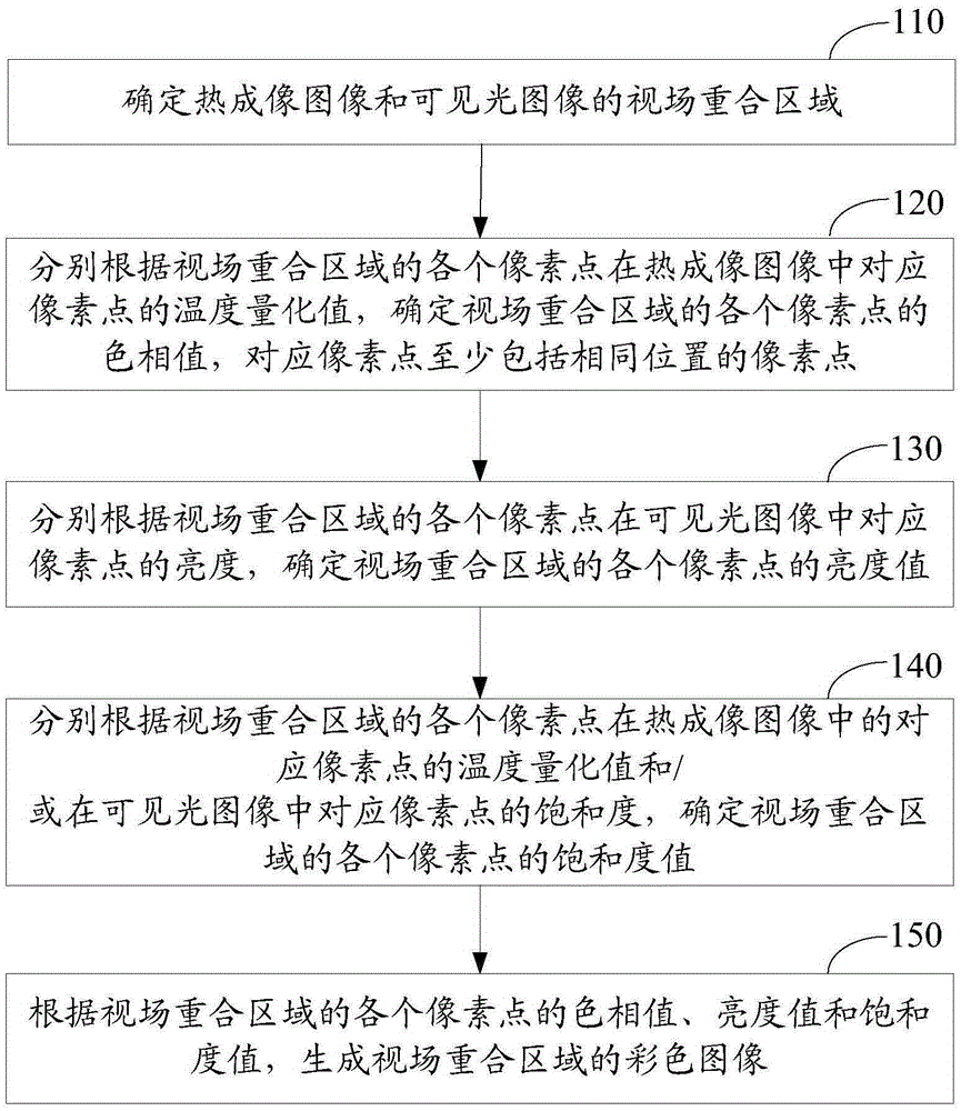
[0042] Such as figure 1 As shown, a thermal imaging image processing method provided by an embodiment of the present invention is implemented in the following manner:

[0043] Step 110: Determine the overlapping area of ​​the field of view of the thermal imaging image and the visible light image.

[0044] Wherein, in the area where the field of view overlaps, the pixels of the thermal imaging image correspond to the pixels of the visible light image one by one, and they all correspond to the same environmental point in the scene.

[0045] Optionally, in the above-mentioned step 110, the overlapping area of ​​the visual field of the thermal imaging image and the visible light image is determined by means of registration. Of course, other ways can also be used to obtain the overlappin...


PUM


Abstract

An embodiment of the invention discloses a thermal imaging image processing method and device. The method comprises the following steps: determining a view field overlap area of a thermal imaging image and a visible light image; determining hue value of each pixel point in the view field overlap area according to temperature quantized value of each pixel point in the view field overlap area in the corresponding pixel point in the thermal imaging image; determining brightness value of each pixel point in the view field overlap area according to the brightness of each pixel point in the view field overlap area in the corresponding pixel point in the visible light image; determining saturability value of each pixel point in the view field overlap area according to the temperature quantized value of each pixel point in the view field overlap area in the corresponding pixel point in the thermal imaging image and / or saturability in the corresponding pixel point in the visible light image; and generating a color image of the view field overlap area according to the hue value, brightness value and saturability value of each pixel point in the view field overlap area. The scheme can distinguish details of a target, and improves identification degree of the target.

Description

technical field [0001] The invention relates to the technical field of image processing, in particular to a thermal imaging image processing method and device. Background technique [0002] The temperature measured by the thermal imaging device is generally quantified and normalized to obtain a discrete value [0, 255], which is hereinafter referred to as the temperature quantization value. Therefore, the measurement result of the target scene is presented as a grayscale image. In order to more clearly show the temperature distribution characteristics in the target scene, different temperature quantization values ​​can be mapped to corresponding colors through a "temperature quantization value-color" lookup table to obtain a color image. This kind of image shows the distribution of temperature data more clearly and vividly. However, due to the low resolution of the thermal imaging image itself, the details such as edges in the image are seriously missing, and it is difficult ...

Claims


Application Information

Patent Timeline
Patent Type & Authority Applications(China)
IPC IPC(8): H04N5/33H04N9/64G06T7/00
CPCH04N5/33H04N9/64G06T2207/10048G06T5/50G06T2207/10024G06T2207/20221H04N23/11G06T11/001G06T2207/10016
Inventor 卢维李乾坤
Owner ZHEJIANG DAHUA TECH CO LTD
Why Eureka
Try Eureka