Rotation thread unwinding mechanism

A technology for unscrewing and injection molding machine, applied in the field of injection molding, can solve the problems of long time consumption and low work efficiency, and achieve the effect of high work efficiency and shortening of unscrewing time.

Inactive Publication Date: 2016-02-24
CHONGQING RUITING PLASTIC
View PDF0 Cites 1 Cited by
  • Summary
  • Abstract
  • Description
  • Claims
  • Application Information

AI Technical Summary

Problems solved by technology

[0003] However, since the threaded injection molded part and the threaded core are in a threaded state, after the mold is opened, the injection molded part needs to be removed from the injection cavity by rotating the threaded core along its thread. The current threaded core stripping method The main method is to manually twist the threaded core so that the threaded core withdraws from the threaded part of the injection molded part. This method of thread removal takes a long time and the work efficiency is low.

Method used


Image

  • Rotation thread unwinding mechanism

Examples


Embodiment Construction

[0012] The present invention will be described in further detail below by means of specific embodiments:

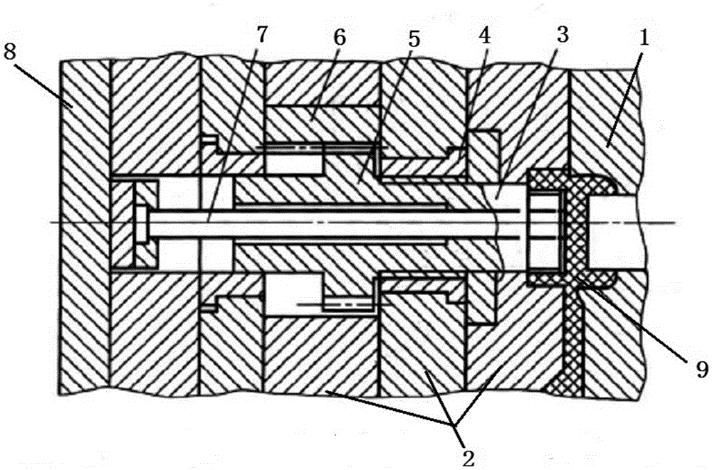
[0013] The reference signs in the accompanying drawings of the description include: fixed mold 1, movable mold 2, movable core 3, guide sleeve 4, core gear 5, driving rack 6, center push rod 7, push plate 8, injection cavity 9.

[0014] Embodiment Rotation unthreading mechanism is basically as attached figure 1 Shown: The rotary unthreading mechanism is set on the injection molding machine. The injection molding machine includes a fixed mold 1 and a movable mold 2. The right end of the fixed mold 1 has a half groove, and the left end of the movable mold 2 has a half groove. After the fixed mold 1 is combined, an injection molding cavity 9 is formed between the two half grooves.

[0015] The inside of the fixed mold 1 is provided with a mounting groove transversely penetrating through the fixed mold 1 , and the right end of the mounting groove communicates with the inject...


PUM


Abstract

The invention belongs to the technical field of injection-molding technologies, and particularly discloses a rotation thread unwinding mechanism. The rotation thread unwinding mechanism is arranged on a die of an injection-molding machine, the die comprises a fixed die body and a movable die body, a semi groove is formed in the right end of the fixed die body, and a semi groove is formed in the left end of the movable die body; after the movable die body and the fixed die body are oppositely combined, an injection-molding cavity is formed between the two semi grooves, a transversely-penetrating installation groove is formed inside the fixed die body, a guide sleeve is arranged in the installation groove in an interference fit manner, and a movable mold core is arranged inside the guide sleeve in a threaded fit manner; and a mold core gear is arranged on the external circle of the movable core, a movable driving rack perpendicular to the installation groove is arranged inside the fixed die body, and the driving rack is meshed with the mold core gear. By means of the rotation thread unwinding mechanism, the thread unwinding time of the threaded core is shortened, and the working efficiency is higher.

Description

technical field [0001] The invention belongs to the technical field of injection molding. Background technique [0002] Injection mold is a tool for producing plastic products, and it is also a tool for giving plastic products complete structure and precise dimensions. Its use method is to inject the heated and melted material into the cavity of the injection mold under high pressure, and after cooling and solidifying, a molded product is obtained. When the existing injection molded parts need to be manufactured with threads, it is necessary to put a threaded core in the injection mold, and after the injection molding is completed, the threaded injection molded parts will come out. [0003] However, since the threaded injection molded part and the threaded core are in a threaded state, after the mold is opened, the injection molded part needs to be removed from the injection cavity by rotating the threaded core along its thread. The current threaded core stripping method T...

Claims


Application Information

Patent Timeline
Patent Type & Authority Applications(China)
IPC IPC(8): B29C45/40B29C45/26
CPCB29C45/40B29C45/26
Inventor 毛德中
Owner CHONGQING RUITING PLASTIC
Why Eureka
Try Eureka